FabMouse
This page is part of the MCP 2013/14 class. It was supervised by René Bohne.
Team members: Verena Kuhr, Marty Pye, Claude Bemtgen, Andrii Matviienko, Ravi Kanth
Abstract
Our basic idea was to make a mouse which is not only usable for normal 2D interactions on a computer (like browsing, or using different programs). It should also be able to interact with 3D objects, which the user manipulates with a 3D software. When both these interaction techniques are combined, the user has a mouse suitable for all programs without changing devices, which costs time and could limit the concentration.
Having this is mind, two aspects are of importance: The mouse housing and the hardware.
Mouse Housing The mouse housing should not only be suitable for normal mouse movements, but also comfortable for 3D interactions in the air. Therefore, the design should be easy to pick up and manoeuvre in midair, as well as being comfortable to grip and hold for a while. Holes on the side can support this.
The mouse should also be customisable to fit in the hands of different users.
Hardware The hardware has to include not only a mouse sensor and additions for 2D interactions, but also additional hardware for 3D interaction. This must be small enough to fit in the housing as well as being light weight for comfortable midair interaction.
For the 3D interaction, an accelerometer and a gyroscope are needed to get the data to compute the orientation of the mouse in midair. A bluetooth module is also needed to transfer the data to the computer/ system.
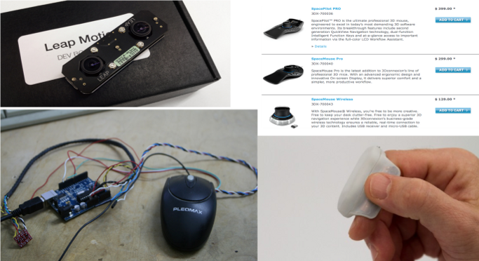
Related Work
- Existing 3D mice mostly require one to learn new interaction techniques, even for 2D movement
- The user might have to switch devices as many are used to the normal mouse for 2D interaction
- Some of them are quite expensive as well
- Some users have attempted projects but not fully realised or properly documented
- This tutorial helped us interface the optical sensor of the mouse with an Arduino.
Iteration: Mouse Housing
To get our final version of the mouse housing, the design went through several iterations. It started with a paper prototype, continued with an "apple" prototype and had several changes in OpenSCAD.
Paper Prototype
We started with a paper prototype as you can see in figure 1. The left and the right button work as normal mouse buttons. The middle button is there to switch between 2D and 3D mode and therefore send values of the gyroscope additional to the accelerometer and light sensor values. The scrolling function should be covered by tilding the mouse.
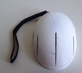
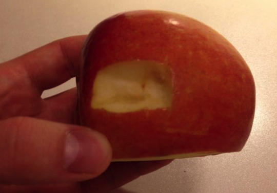
Apple Prototype
According to that the paper prototype and to first test the mouse for better midair usage, we made an apple prototype.
OpenSCAD Versions
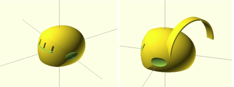
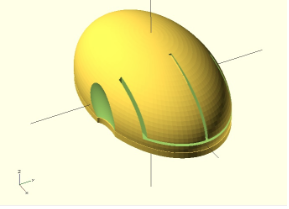
First General Form Produced with OpenSCAD To get the STL model of the whole mouse, several forms were combined. The front part of the mouse is made of the intersection of two ellipsoids with a difference of 90 degrees and cut back of the intersection with a cube. The back part is made of one ellipsoid, which is cut with a cube in the front. The whole cabinet is cut on the bottom with a cube. The inside part is cut out with the scaled main cabinet. The thumb hole is cut out using an ellipsoid. And the buttons are cut out using four vertical parallelepipeds and one horizontal.
1st Version Having this in mind we constructed the first STL version that can be seen in figure 3. We also thought of an optional handle to make it easier for midair interaction. However, the design was a little bit too round, it was uncomfortable to press the buttons and the handle in that form not really necessary.
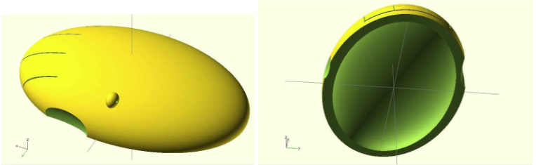
2nd Version These flaws were changed in the following design. (See Figure 4) The housing is flatter, the buttons are longer, and a hole is added on the side to give the end user the possibility to add a security ribbon. The housing itself also has thinner walls so as to have more space for the hardware.
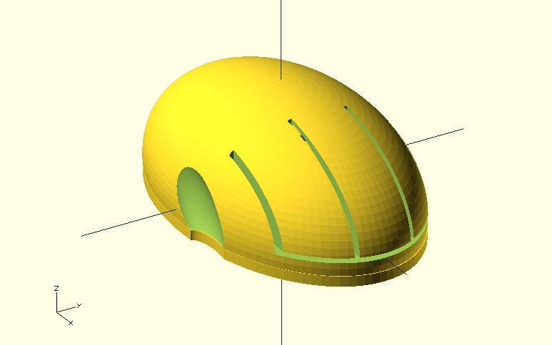
3rd Version On the third STL model, like it can be seen in figure 5, the security ribbon is on the back of the mouse for better usability and to not disturb the user while working. We also added a bottom part with clips, so that it can be connected easily to the top part.
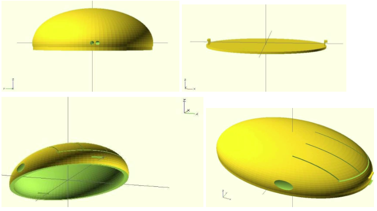
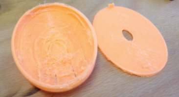
On this progress level, we printed our first model. However, according to the possibilities of the Rostock, the 3D printer was not able to print the clips precisely. So these clips were not strong enough to hold the bottom part and the top part together. (See Figure 6)
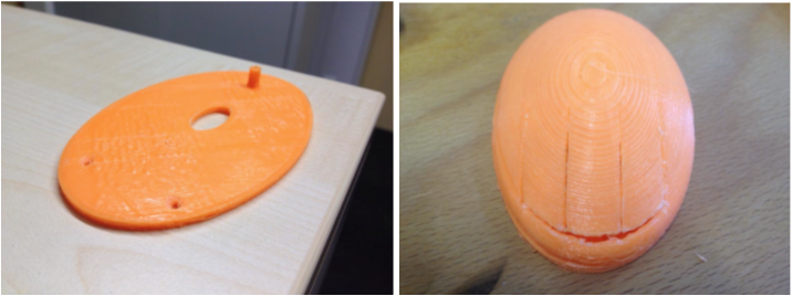
4th Version According to the problem with the third version, the fourth STL model has a changed bottom part. (See Figure 7) Therefore, we decided to have holes on the bottom as well as on the top part to screw these parts together.
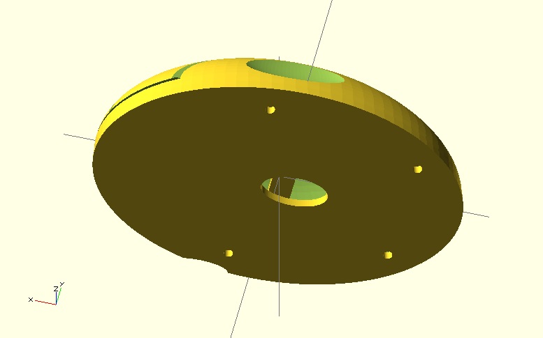
This version could be printed precisely enough on the RepRap to hold the bottom and top part together. (See Figure 8)
Final Version of Housing
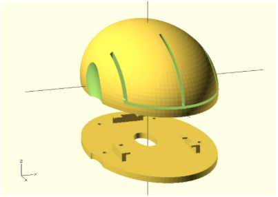
For the final STL model a supporting structure was added to the bottom part so that the hardware part will stay on its place while moving the mouse in all different directions. (See Figure 9-B) The bottom is connected to the top via four screws. Furthermore, we eliminated the middle button. Now, the user can switch between 2D and 3D mode by simultaneous pressing left and right button. The hole on the side for the little finger is changed for more convenient support in the air.(See Figure 9-A)
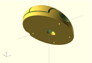
Final Form Produced with OpenSCAD The main part is made of two ellipsoids. Smaller ellipsoid is cut out of the bigger one and the bottom part is cut with a cube. The buttons are made by cutting out thin cubes, holders for thumb and little finger by ellipsoids and holes for the strip on the back part by cylinder. 4 holes for screws are made of cylinders with cut out cylinders inside and connected via additional polygons to the inside part of the wall.
Customisable Parts According our final prototype we defined the following parameters as being customisable:
Customisable parts of the bottom:
- Bottom Back Connector Position
- Bottom Left Connector Position
- Bottom Right Connector Position
- Bottom Length
- Bottom Width
- Bottom Height
- Bottom Hole Radius
- Bottom Hole Length
- Bottom Hole Width
- Screw Hole Size
Customisable parts of the top:
- Ellipse Length
- Ellipse Width
- Ellipse Height
- Thickness Of The Walls
- Screw Hole Size
- Thumb Size
Problems & Solutions while Printing Several problems occurred while printing. All problems were caused by home 3D printers, which are not precise enough for some shapes and do not work with support material. The biggest problems and our solution are shown in table 1.
| Problem | Solution |
|---|---|
| With an absence of a supporting material in home 3D printers, clips to hold button and top part together are not able to hold a bottom. It is fragile and easy breakable. | Therefore we decided to use holes to screw bottom and top part together. |
| After printing a bottom part one still needs to cut out holes for screw with knife, because home 3D-printers are not precise enough and holes are usually smaller than expected. | Using smaller screw will solve that problem. However, a post-processing step might be necessary. |
| As far as the top part has a small contact area it is hard to make it stable enough, even though the plate of the printer is hot. | To decrease the possibility to get an unstable housing, we rotated the top part in the STL file for printing. |
| Support material is not used yet for home 3D printers, therefore the quality of fragile parts (button sticks) and buttons is not good. | At the end additional cutting or gluing is required. |
| Quality of the bottom parts is not sufficient as might be seen on the pictures above. | The form we finally created is less accident-sensitive and will help to get the best possible result with a home 3D printer. |
Table 1: Problems and solutions while printing.
We constructed our mouse in a way, which makes it also possible for people with a home printer to print their FabMouse on their own. However, professional 3D printers show better results and no finishing process will be needed.
IMPORTANT In general two post processing steps are necessary: the button sticks need to be cut to the needed length and the holes for screws should be adjusted to the depth of the screws you choose.
Iteration: Hardware
As well as we had some iterations to find the final version of the mouse, we also had iterations in finding the final hardware which fit the best for our needs and in our housing.
Bluetooth Sensor We assembled the bluetooth sensor and connected it with the computer like it is explained in “Step by step instruction”. Figure 10 shows the result.
.JPG)
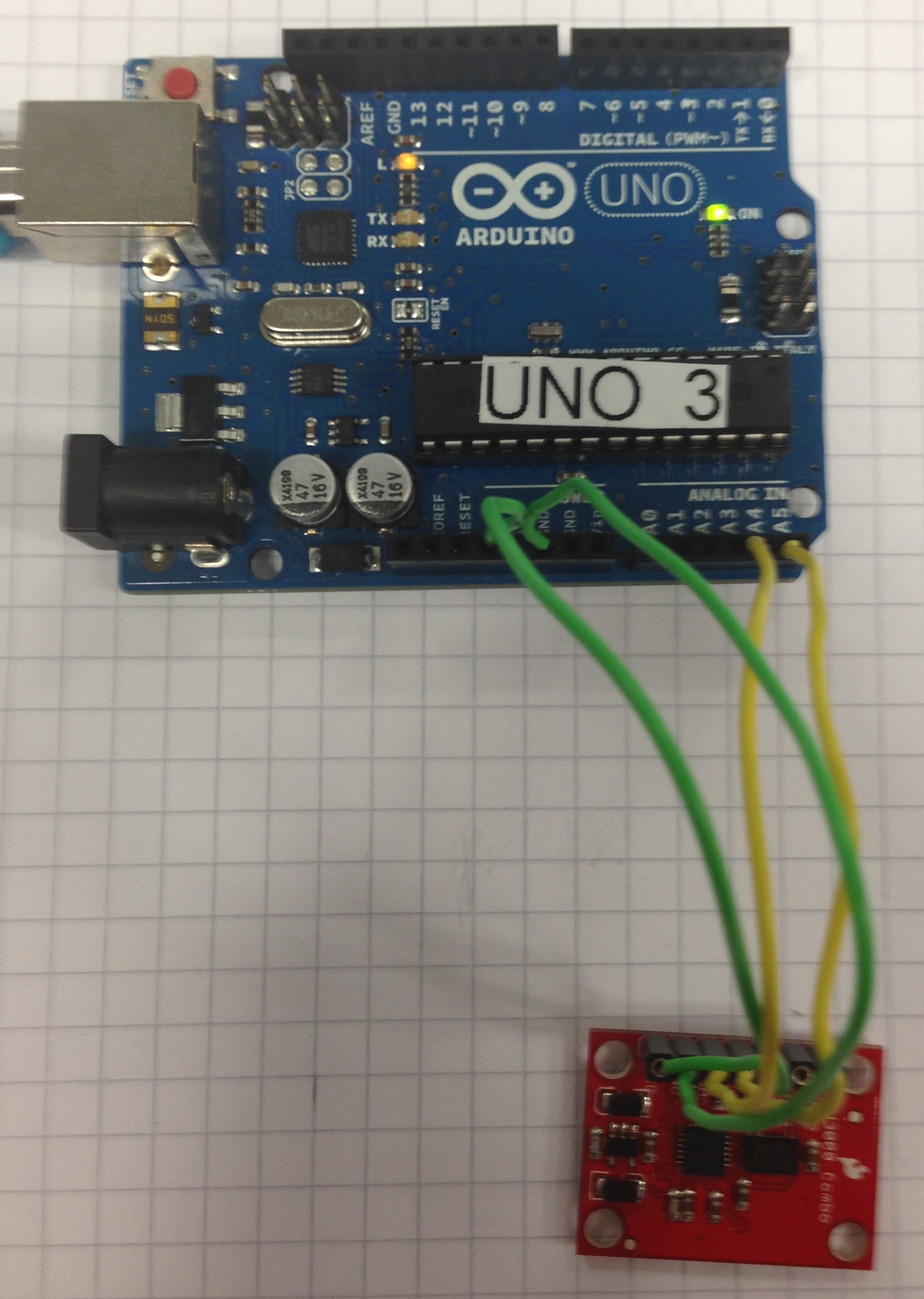
Arduino with IMU Fusion Board We assembled the Arduino with the IMU Fusion board. In Figure 11, the result is shown. We did that to check whether the board is precise enough for mouse interaction. We got values of the accelerometer and the gyroscope, which aims the needs for this project. However, the Arduino is too big to use it in a mouse, so we ordered a smaller Wattuino to connect with the IMU Fusion board.
Wattuino with FTDI Breakout Reloaded Board To program the Wattuino, a FTDI breakout reloaded board is needed.
Wattuino with IMU Fusion board We allembled the Wattuino with the IMU Fusion Board like it is explained in the “Step by step instruction”. We had difficulties programming the Wattuino, because Watterott had delivered it faulty, and a whole edge of connectors was shortcircuited. After cutting this connections, the Wattuino worked again.
Final Version of Hardware
All components:
- Logitech mouse sensor
- Wattuino
- Bluetooth sensor
- IMU Fusion board
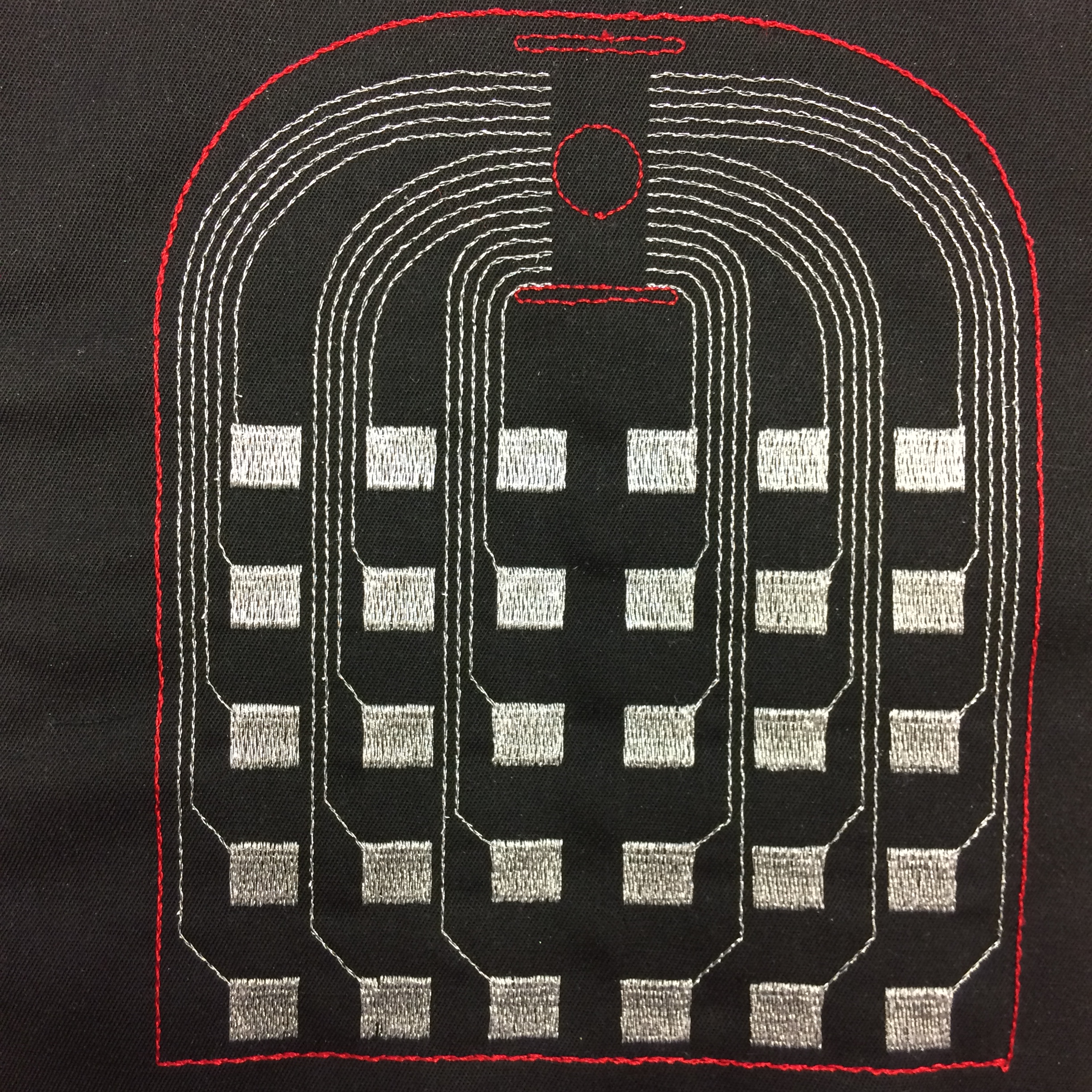
- Our Eagle board.
- Rechargeable battery
For the final mouse, we used an optical sensor from a Logitech mouse. We detached the orignial processing chip from the mouse, and replaced it with a female pinheader. (see Figure 12)
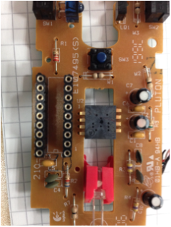
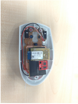
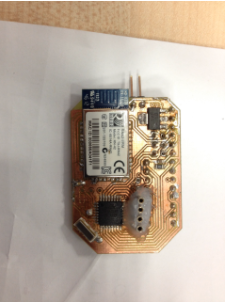
Then we created two different PCBs. Both plug onto the existing mouseboard, like a shield, and add the 3D and bluetooth functionality. The first PCB just plugs the existing bluetooth breakout, gyro and Wattuino onto one PCB. (see Figure 13) This PCB is fully functional.
The second PCB is more optimised. It has an ATMEGA chip soldered straight onto it, same as the HID bluetooth chip. (see Figure 13) This chip is somewhat smaller, but we had problems burning the boot-loader on to the chip. So unfortunately we weren’t able to get this chip working in time.
Software
The accelerometer and gyroscope provide us with raw values which need to be processed and the orientation of the device in 3D space to be computed for us to use the mouse. A detailed explanation to understand how it works can be found here.
After trying to implement a basic version we decided to use the FreeIMU library to interpret the sensor values and provide us with the orientation of the mouse in the form of Euler angles.
There are two different parts for the software. One is the Arduino Code, which runs on the mouse and sends the sensor data over bluetooth. The other is the Processing library, which reads and interprets the data on the computer to handle the 3D interaction. The 3D interaction controls the orientation of an object in 3D space.
Code for Arduino The code for Arduino reacts to our buttons, the tilting (provided by the IMU Fusion board) and the position (provided by the optical sensor). The input data we get from our sensors is then handled and sent to the HID Bluetooth device. The bluetooth module can be set up in different ways, for example as a mouse, a keyboard, a joystick, etc.. Since we wanted to use it as a normal mouse, as well, apart from being as a midair input device, we chose to set it up as a "combo", which combines "mouse" and "keyboard". The keyboard function is then, in a way “hacked”, to control the 3D interaction.
The mouse can alternate in 2D mode (normal mouse interaction) and 3D mode (midair interaction) by pressing both left and right buttons simultaneously. In 2D mode, the Arduino code reads the optical sensor values along with information on the key presses and sends them as a mouse report through the Bluetooth HID.
In 3D mode, the Euler angle values from the IMU Fusion Board are read every 200ms and if there is a change of more than five degrees along any axis, the values are encoded as key presses (Shift+Alt+F1 - F11) to be transmitted through the bluetooth HID as a keyboard report.
Processing Library The processing library code reads the keyboard presses, interprets them as angles in three axes and sends rotate commands accordingly. The library only looks for the F1-F11 keys and decodes them back into the angles as measured by the IMU fusion module. The library provides 2 functions that the end user can use. The first function just decodes the Euler angles and returns a vector containing these three values. The second function looks up if you have rotated over a certain threshold in one direction, and if you did so, it will keep rotating in that direction. Again it will return a vector, but this time, the values have been summed up.
How to use it: First import the library, then in the setup-method create a Fabmouse object (fm = new Fabmouse(this);) and finally in your loop-function, you can get the angles (PVector vect = fm.absoluteRotation();) or the summed up angles (PVector vect = fm.continiousRotation();).
Conclusion
To conclude, we have the following results and observations to be noted while fabricating your own fabmouse.
Mouse housing According to the quality(type) of the 3D printer, different housing qualities can result. We already improved our design, that also non-professional home 3D printers can make a usable housing. However, according to the capabilities of the printer, little variations can occur which can make buttons harder to press due to the high thickness of the housing walls or small distances between the buttons
According to the hardware, the bottom part has to be very flexible. Therefore, the support structure is customizable.
Hardware The hardware was the most problematic part in our project. When soldering several components, we had to be very careful to not destroy any connections. Sadly, we were not able to use the most elegant solution with the hardware with our PCB with an integrated micro-controller and Bluetooth module.We ran into issues with the finished board and components while trying to setup the system. However, for interested users we also uploaded that version of the schema. They could set up and assemble the hardware and try to get it to work. For hardware beginners however, we would recommend the easier method which is explained in our step by step instructions.
Software Since we could only send mouse and key events to the computer and no general data stream, we needed to use unusable key press combinations to send our desired actions. This leaves us with only a few keys(The function keys along with Alt+Shift as modifiers) to represent the angles in 3 dimensions and we used a custom encoding to represent the data to be transmitted. The processing library then has to translate these commands into actions which can be performed. Specific details on how the keyboard is used to send coded data and handled in the library is mentioned in a separate document which can be used as a reference by developers to work on their own plug-ins, modifications for the mouse.
Note: The current key modifiers used with the function keys only work on Mac OS. For windows an alternative set of modifiers need to be used to avoid a combination already in use.
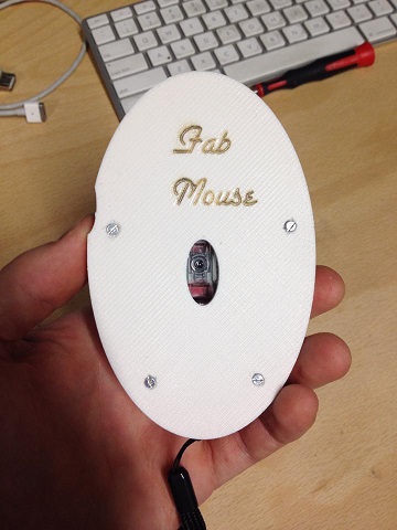
Final FabMouse
Presentation
Final presentation will be on 26th of February. For more information contact René Bohne.
Now Make Your Own FabMouse!
- PDF with step by step instruction will follow
- Link to Thingiverse for customizable housing:
http://www.thingiverse.com/thing:255991
http://www.thingiverse.com/thing:255938
- Link to Thingverse for openSCAD source file:
http://www.thingiverse.com/thing:257387
- Link to Instructables for overall instructions like step by step instructions
http://www.instructables.com/id/3D-Mouse/
- You can also find open SCAD source file attached