Haptic Vest 2.0
[Main Personal Photonics Project Page] | [Haptic Vest 1]
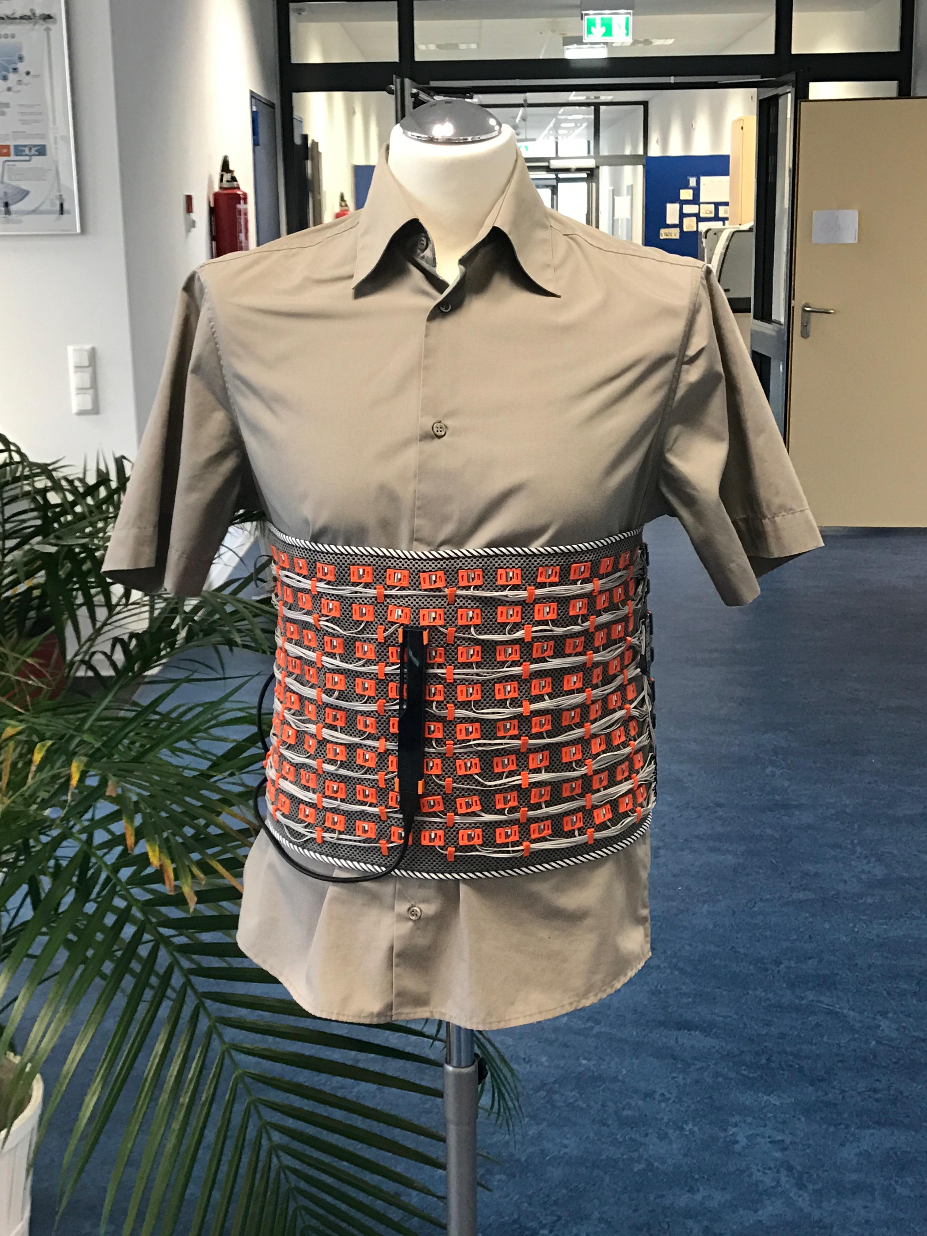
The Haptic Vest 2.0 is a wearable vest that uses a front-facing depth camera and an array of 128 vibration motors to let its wearer feel an image of the obstacles in front of him and their individual distance. It is part of our BMBF-funded project Personal Photonics that aims at making photonic, or optical, technologies like lasers and depth cameras accessible to the DIY maker community.
What does it feel like?
Imagine putting on the Haptic Vest, which is actually more like a tight-fitting, broad belt across your lower chest, then closing your eyes, and starting to walk. As you approach a lamp post that you are in danger of running into with your right shoulder, you start feeling a vertical column of motors vibrating on the right half of the vest. As you move closer, the vibration gets stronger and slowly shifts towards the right. You make a small left turn to correct your course, and the vibrating column moves further to your right, indicating that you will now walk past that lamp post and no longer hit it as you continue walking.
How does it work?
The Haptic Vest is based on earlier work at our lab by David Antón Sánchez' called OpenVNAVI: A Vibrotactile Navigation Aid for the Visually Impaired.
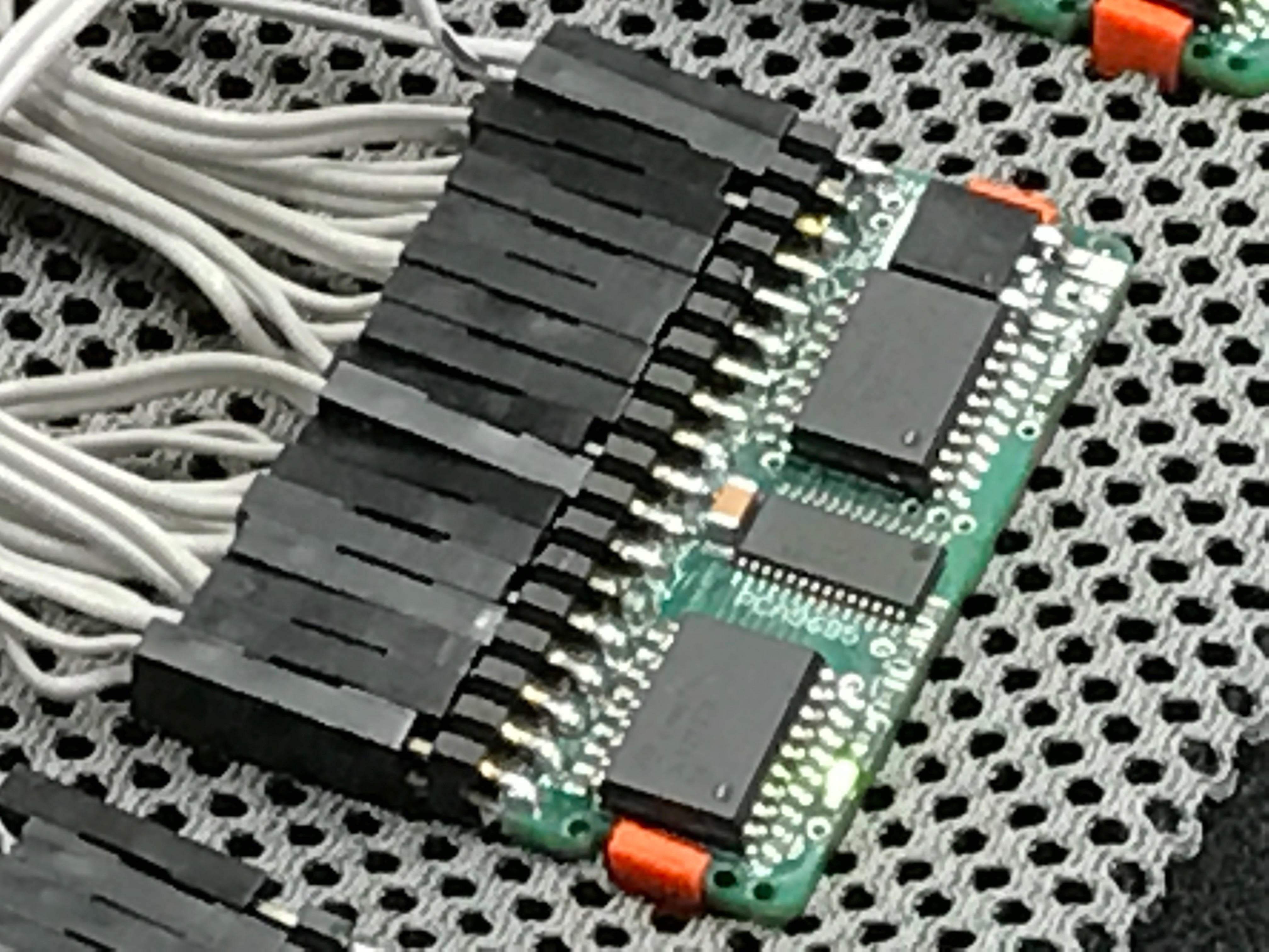
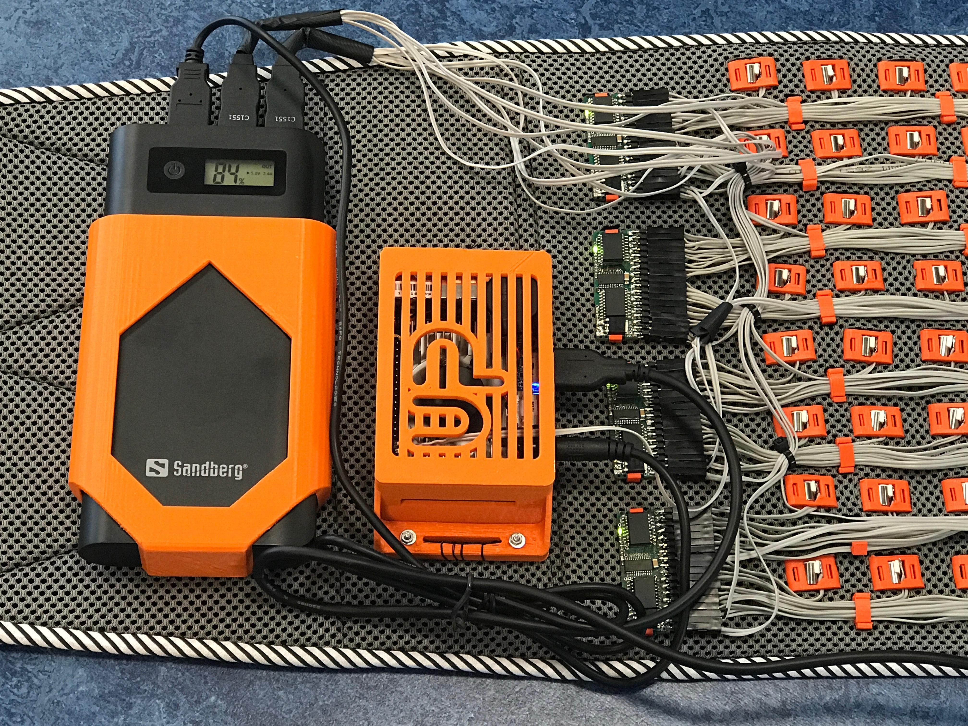
It uses our combined I2C-PWM expander boards with driver circuits for the vibration motors. These boards use a pinheader at the side for crimped connections to the motors and to each other (via I2C) as well as the battery.
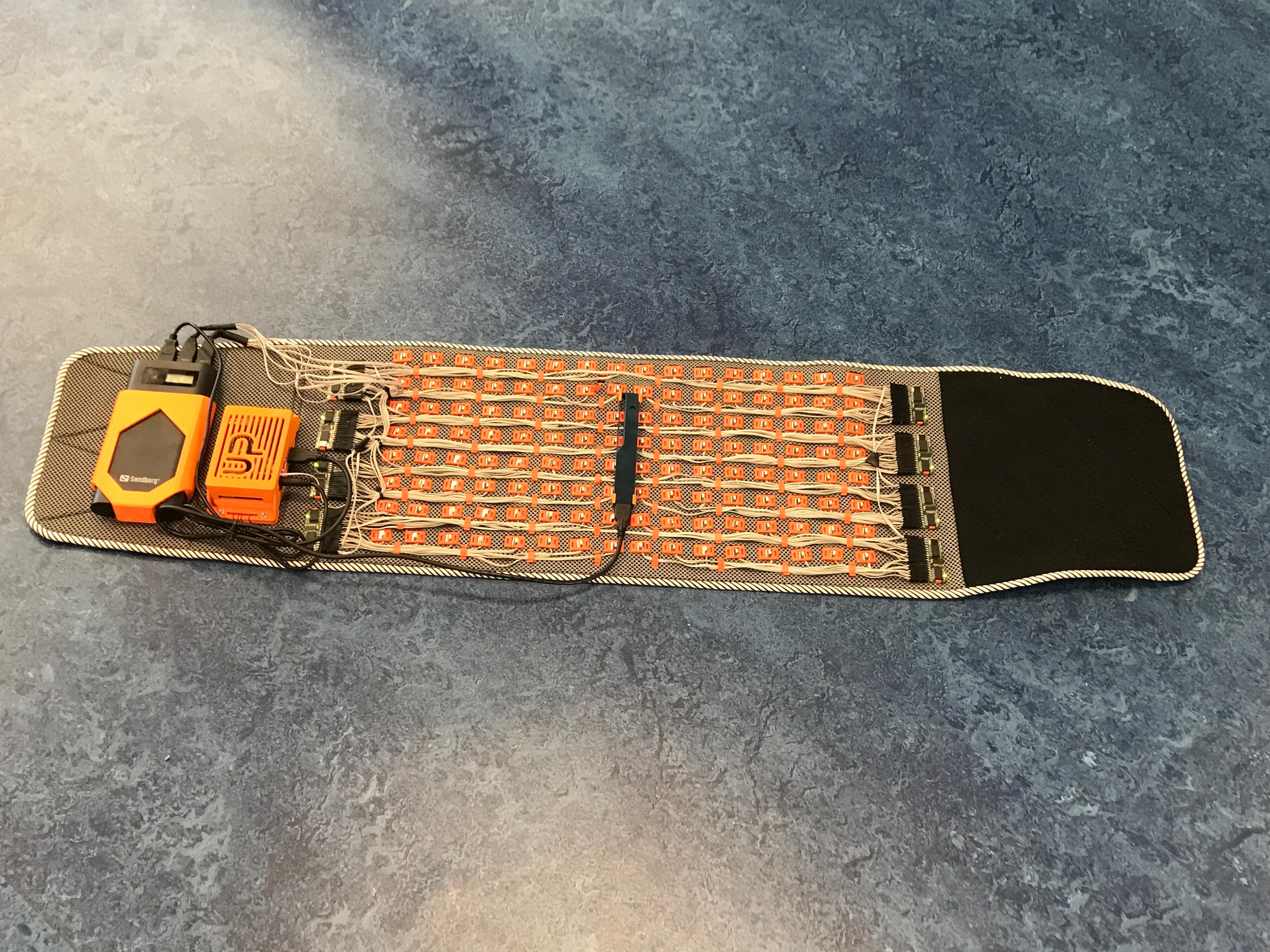
Motors, wiring, and PCBs are held in place with orange 3D-printed plastic clips we designed. The battery and Up board for processing are also enclosed in a 3D-printed housing.
Files for both the PCBs and 3D-printed parts can be found on github. All 3D-printed parts for connecting electronics with the textile are designed to be printable without support structures, so they should print fine even on affordable entry-level 3D printers.
To make the vest, a basic layout is cut into a textile layer (a pre-fabricted vest or waist belt). There's a sample pattern in the GitHub repository linked above. Each vibration motor (5 mm wide, 8 mm long, with encapsulated excenter) is clipped onto the fabric using our 3D-printed motor housings. Standard wires are used to connect them with the driver PCB on each size. Crimped connectors make it easy to swap out faulty motors.
The wires are held in place on the fabric using additional 3D-printed clips. Each PCB gets its own power line to the battery on the back to reduce current stress on the wire, while the I2C lines are bundled at each side and connected to the Up board.
The Up board controls the motors. For the casing, we used a design we found online. A RealSense depth camera is connected to the board via USB 3.0, attached either in the middle of the vibration motor matrix with 3D-printed connectors (to avoid optical parallax errors), or elsewhere on the user's clothing if that position isn't appropriate for your use case.
A more detailed description is in the works.