Milling PCBs with the Protomat S104
Safety Notes - READ THIS!
- If anything goes wrong, you can stop the machine by lifting the plexiglass lid.
- The FR4 material that is used for the pcbs contains glass. To avoid damage to your lungs via microscopic glass shards, wear a filtering mask when post-processing the pcbs!
- When cleaning up, use the "NT 30/1 Tact Te" Industrial vacuum cleaner! The other vacuum cleaners don't have proper filters for the mircoscopic glass shards and you will just blow the shards into the air for everybody to breathe.
If you have questions regarding safety issues, ask an employee at the lab!
General Note:
The software that has to be used in order to control the Protomat is unstable and not really user-friendly. If you run into trouble, check the FAQ at the bottom of the page, ask the Hiwis in the Lab, or write the person that is responsible for the Protomat.
The following steps are to be performed in the given order. If you make a mistake or something doesn't work quite right, it's often best to just start over with the whole process. That will also avoid crashing of the software as it seems to have trouble to handle unexpected order of steps.
Things that are displayed with a violet background like this are only important for processing double-sided pcbs and should be ignored for single-sided processes.
Starting the Machine
Check if the pressure gauge on the compressor shows at least 6 bar. 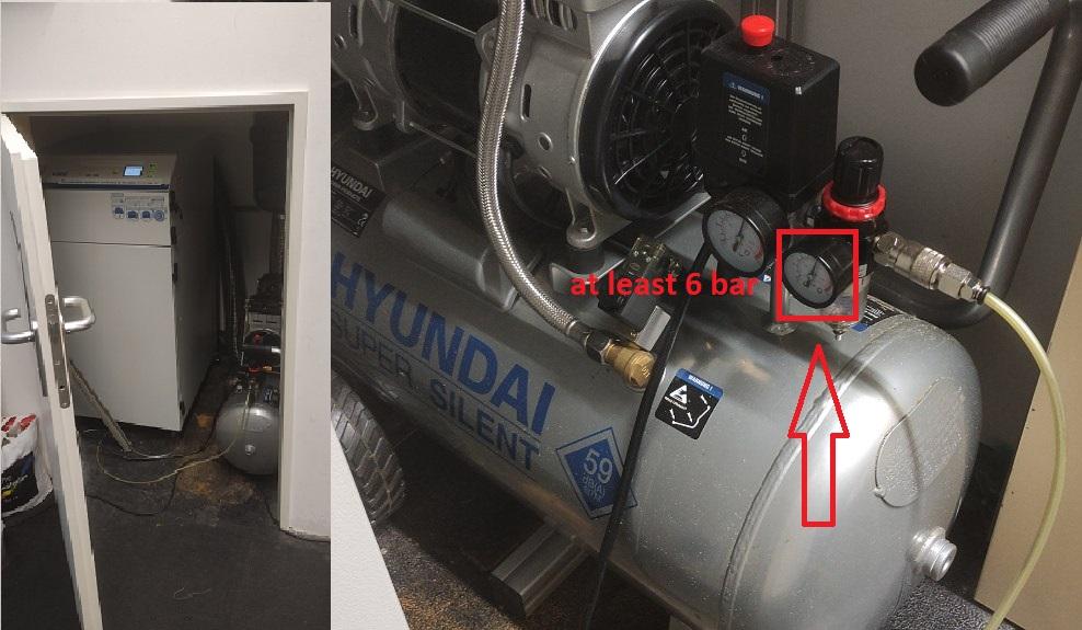
If at least 6 bar are available you can then turn on the Protomat. You can find the on-switch at the backside of the protomat on the left side. (see pictures)
Flip the switch and the machine will turn on.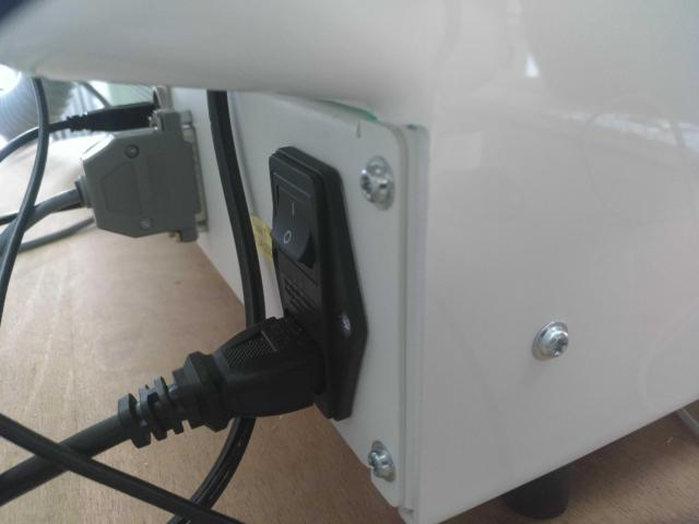

Now you can start the "Circuit Pro" software on the Mac. The shortcut for "Circuit Pro" is located on the desktop. The software will then initialize the Protomat which can take a minute or two.
If the machine doesn't connect automatically, you can do so later via "Machining -> Connect -> ProtoMat S104"
Preparing the Job
After Circuit Pro finishes the initialisation of the Protomat, you will be prompted for choosing a template. Click on "Custom Template" and choose one of the files from the "LPKF Profiles" folder on the Desktop. The template should suit your pcb design and it is is vital that you choose the correct one for your project. As a guide for which design requires which template, you can take a look at the following table:
| Template | Function |
| SingleSidedTop | For pcbs that only use the top copper layer. Usually the SMD-components would be placed on the top side of the pcb and the THT-components on the bottom side. For the use of single-sided copper clads. |
| SingleSidedBottom | For pcbs that only use the bottom copper layer. Usually the SMD-components would be placed on the bottom side of the pcb and the THT-components on the top side. For the use of single-sided copper clads. |
| DoubleSided | For pcbs that need to use two layers of copper. These are more error-prone and time-consuming to produce and in addition you will need to use double-sided copper clads which are more expensive. The process for double sided pcbs also requires additional manual steps that are marked by a violet background. |
After picking the template file, you can import your gerber and drill files. To do so, click on the "Import data from a non-native format" button. (see picture)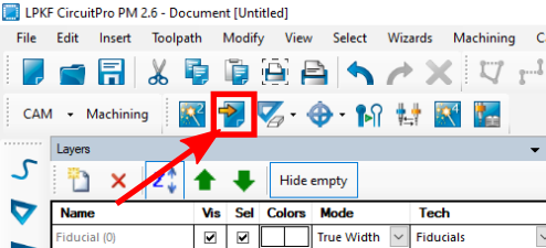
The import window will prompt you for your files. Choose the gerber files and the (exellion) drill files of the design that you want to realize. After choosing single files, you can always import another file by clicking on the "Add file" button. After all needed files have been imported, you have to assign them to their resprective layer by selecting it via the item picker. (see picture)
For files exported from KiCad or Eagle, the assignment should happen automatically.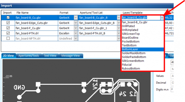
As soon as all layers are assigned, click on the "Ok" button to import the files. You should now see your design in the main view.
If you are creating a double-sided pcb, you need to add fiducals to the board. To do that, click on the "Fiducals" button in the toolbar. (see picture)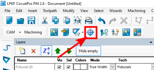
Choose the option "Fiducal...". You can now place fiducals by clicking in the main view. (see pictures) You will need to place at least two of them. They work best when placed in opposing corners.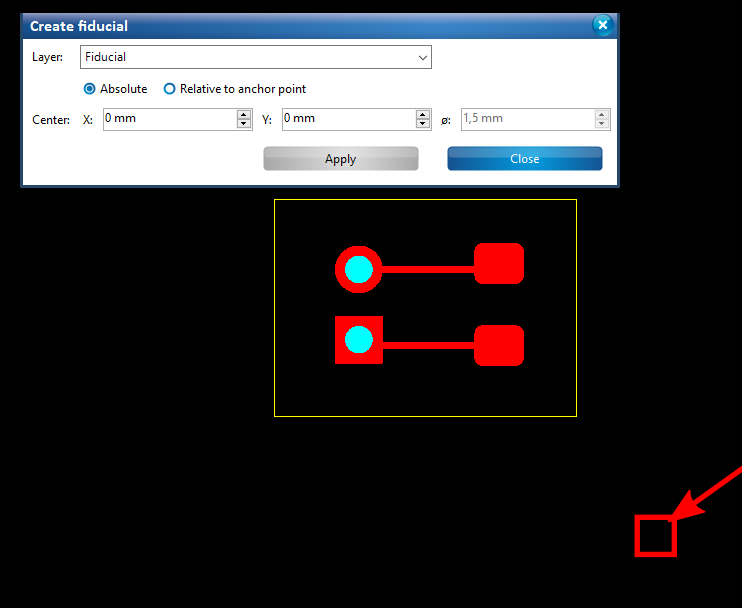
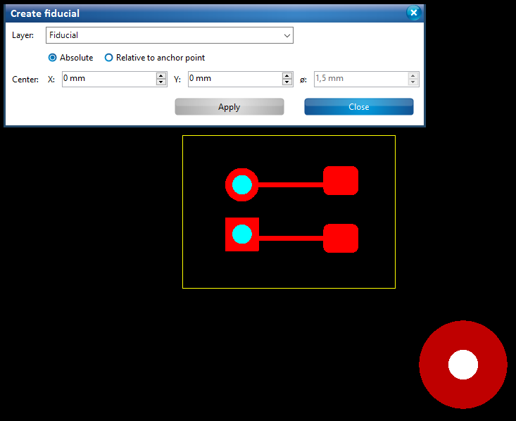
After you place the fiducals you can click on the blue "Close" button.
If your PCB needs a rubout area (complete removal of excess copper) for easier soldering or preventing shorts then you have to add this before generating the tool paths.
For doing so you have to click the symbol with the rubber on the top side and then just draw a rectangle that contains every area that should have a rubout. You can also create multiple rubout areas if you want to keep the copper layer on specific parts of your pcb.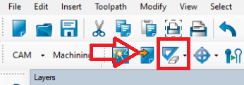
Now click on the "Generate isolation and contour routing toolpath" button (see picture).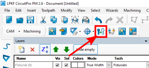
The "Technology Dialog" should now open. Please make sure that all values and checkboxes are set as seen in the picture below. If you have created one or multiple rubout layers for your pcb you have to select the option "rubout layers" in the rubout selection area. Only select the 0,1mm Microcutter if you absolutely need it as this tool easily breaks.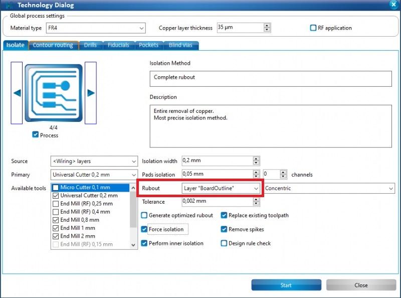
Click the "Ok" button on the pop-up window and you should be able to see the toolpaths that were generated in the main view.
Executing the Job
First of all, you have to make sure that the correct material is used. For single-sided pcbs, a single sided copper clad should also be used. For double-sided pcbs, a double-sided copper clad must be used. If you are unsure what material is currently placed on the milling bed, you can follow this tutorial to remove the material and put it back after checking the underside.
Then switch to the machining view by clicking on the "Machining view" tab. (see left picture)
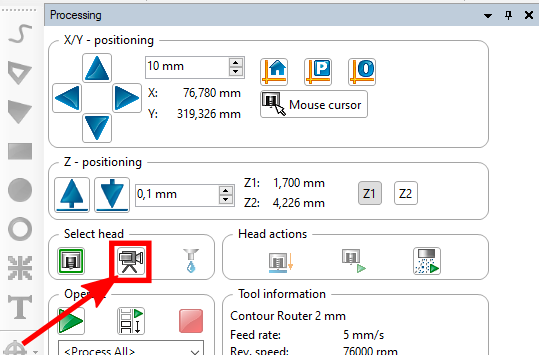
You have to select the camera head by clicking on its icon. (see right picture) This is important! Otherwise the camera will not be at the position of the cursor later and the positioning of the desing will be error-prone. 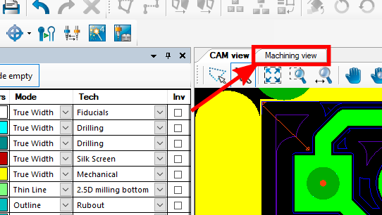
To start milling your pcb, click on the "Board Production Wizard" button. (see picture)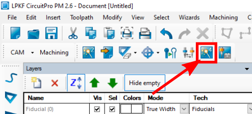
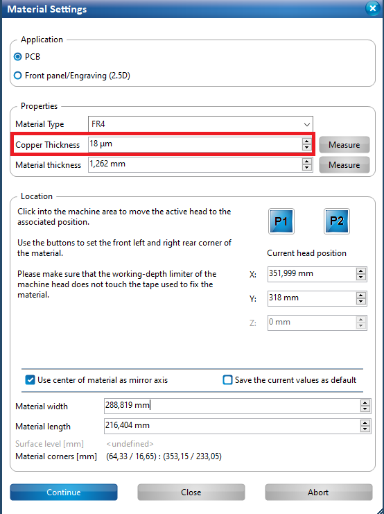
In the following window click on the blue "Start" button, which will lead you to the "Material Settings" window. Make sure the material thickness is set as in the picture below, for the copper thickness you have to choose 75 μm, only then the rubout area will be clear of all copper.
Now click on the blue "Continue" button. A window with the title "Placement" should appear. By dragging with the mouse, you can now move around your design in the main view.
Be careful with the placement of the design! You should find a spot that fullfills all of the following requirements to avoid damage to the machine and the tools and to waste as little material as possible:
- The design fits with a margin of at least 0.5cm on each side and has an extra space of about 3x3cm on one side.
- It has no cuts or holes from previous milling.
- There is a margin of at least a 3cm to the tape at the border of the material.
- The area is reasonably clean.
If the material is dirty, you can clean it with the NT 30/1 Tact Te" Industrial vacuum cleaner and/or a wet paper towel.
To help with the placement you can use the onboard camera of the Protomat. By clicking on the "Mouse cursor" button, you can activate a mode where the milling head (with the camera attached) is moved to any position in the main view that you click on. (see picture)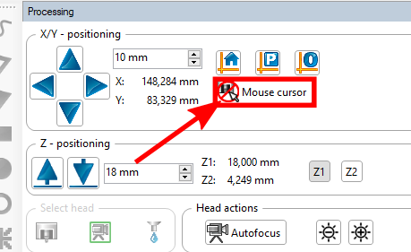
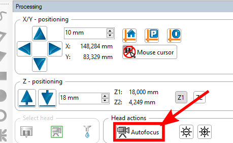
If the milling head is positioned somewhere on the copper, you can focus the camera by moving the printing head up and down with the respective buttons. (see left picture)
A good focus can be achieved at a hight of Z1 = 18.000 mm. You can also use the Autofocus function of CircuitPro, but that's slow and will also focus on anything thats below the camera instead of always focusing the copper clad. (see right picture)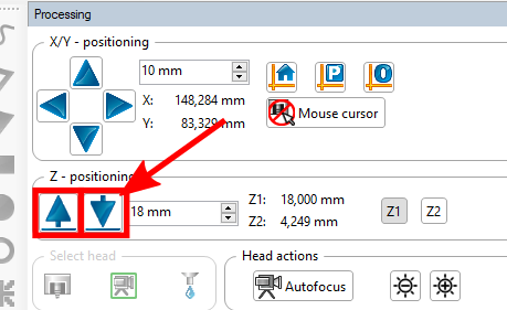
Moving the head around and looking for the edges of previous cuts and the base material itself, you should be able to find a suitable spot for your design. Make sure that you turn of the movement mode by clicking on the "Mouse cursor" button again before you move your design.
When you're done, click on the "Continue" button of the placement window. (see picture)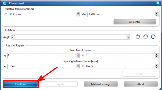
The process should now start right away. Later on you will be asked once or twice to define an area where the machine can test its cutting width. For that move the yellow area to the bottom of the 3x3cm area that you left free during the placement. You move the area by clicking in the main view. (see picture) Make sure to leave enough place for a second machine area when you place the first one! If you're happy with the placement of the machine area, click on the blue "OK" button.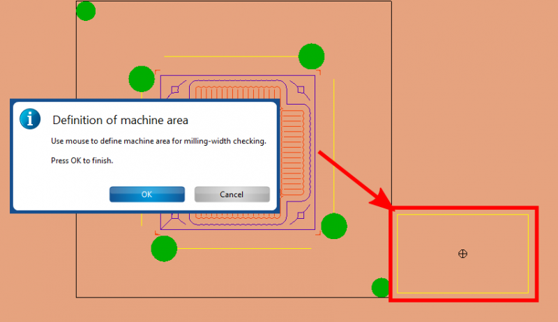
When prompted with pop-ups during the test cuts, just choose the blue option if you don't know what to do.
If you're creating a double-sided pcb, you will eventually be asked to flip the material. (see picture)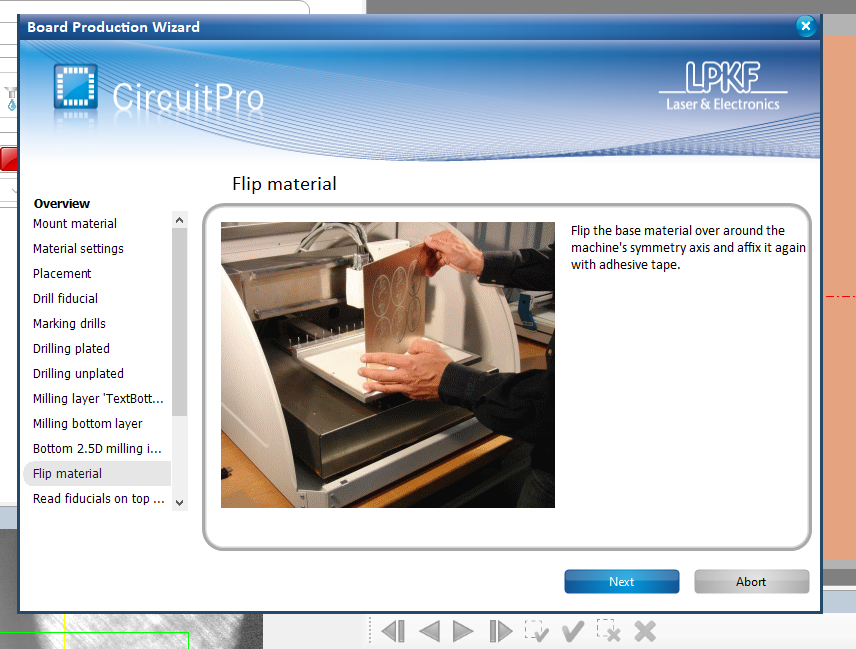
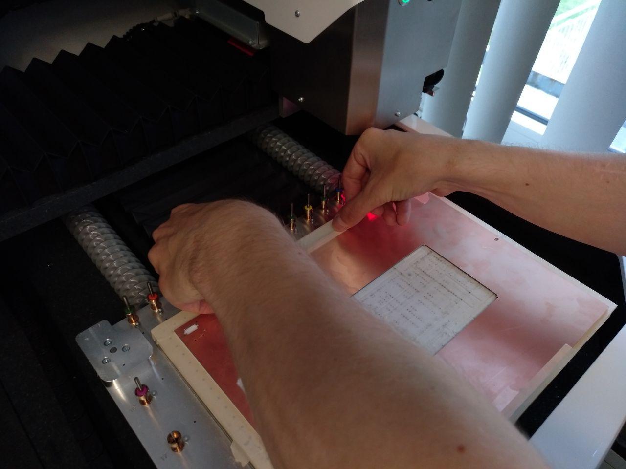
At that point, open up the plexiglas lid of the Protomat, and remove the adhesive tape from the base material. (see picture) Make sure to only remove the tape that is attached to the material and not the tape that is only attached to the milling bed!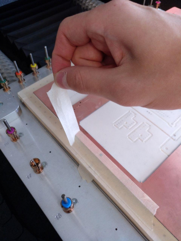
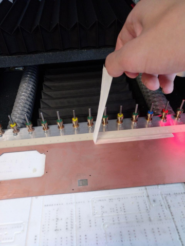
Then remove the tape that holds the foam mat and the material together.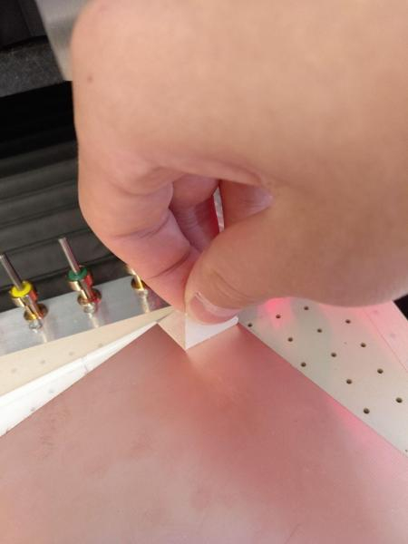
Flip the material around the long axis and use tape to fix the sheet of foam back to the material. Then, fix the material to the milling bed with additional tape. (see pictures) Make sure to exactly align the material inside of the rectangle of tape!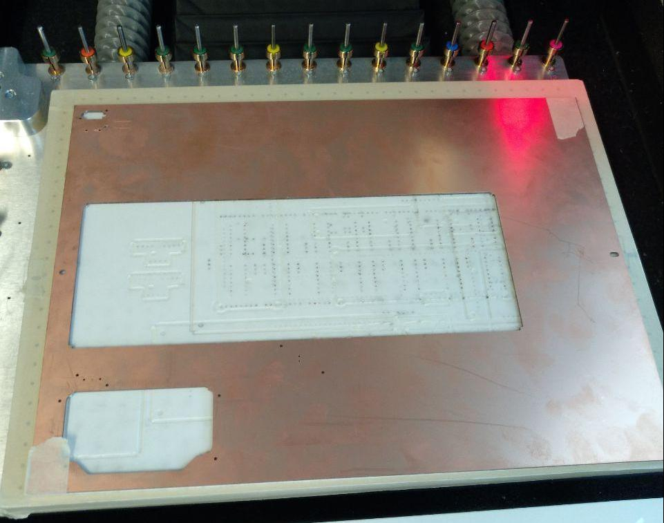
When the material is taped to the bed on all four sides, click on the blue "Next" button to continue milling.
If everything works out, you should end up with a finished pcb after the machine finished. If you want to apply solderpaste now, follow the steps of the dispensing turorial now.
You can cut the pcb loose from the base material with a pair of pincers. Before soldering the pcb, it's recommended to rub the copper traces with some abrasive cloth from the box labelled "PCB Finish". You can find the box in the cupboard above the Protomat. (see picture)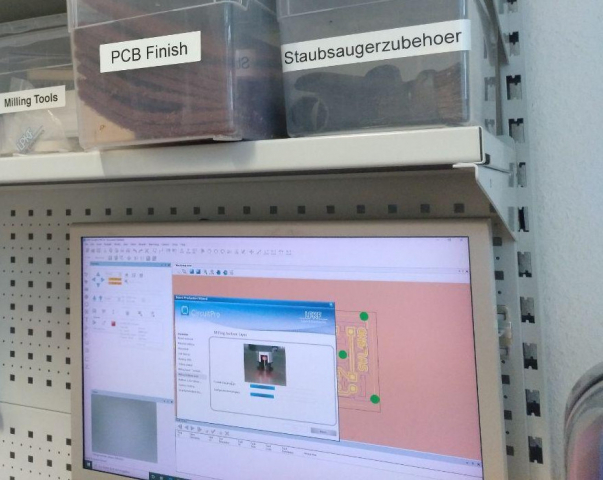
Shutting down the Machine
First, turn off the compressor by rotating the black knob counterclockwise.
To shut the machine down click on the "X" button of the CircuitPro Window. (see picture)
The machine will then move the milling head to a save position. When all CircuitPro Windows are closed, you can switch the Protomat off with the switch on the backside of the machine. 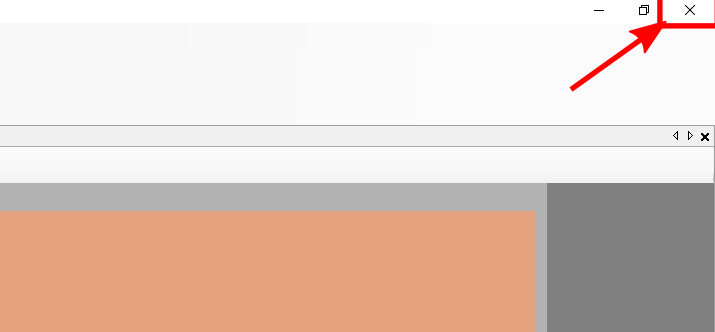
Frequently Asked Questions
- Cicuit Pro just crashed but the machine is still turned on. What should I do?
Answer: Just start Circuit Pro again. You will loose all your progress but the machine should be reinitialized. - The Machine told me that the tool life is expired. How do I replace it?
Answer: Please write an email to the responsible Fablab Hiwi and then click on "ignore" as the tool will probably do a decent job for one more time.