Stepcraft with Fusion 360 and UCCNC
The Stepcraft is suited for milling of 2D and 3D models with materials such as wood or aluminium.Table of Contents
The following documentation is divided into the following topics:- Preparation of the CNC mill
- Preparation of the 3D model / CNC mill machine path
- Loading the compiled gcode into UCCNC
- Running the milling process
- Technical info
Preparation of the CNC mill (Go to top)
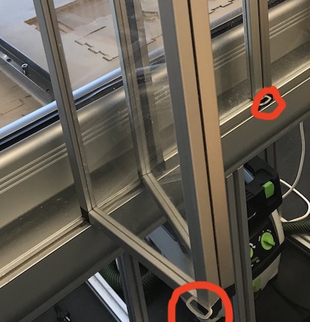
- Open the doors of the enclosure by pulling at one or two rings
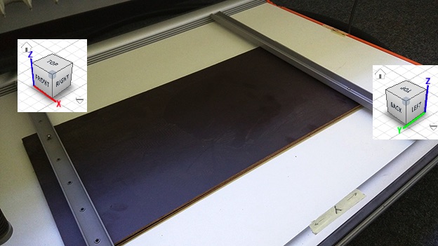
- At first both materials are placed onto the working surface, whereas the sacrificial plate is to be put down first and on top of it the actual working piece material.
+Additionally screws should be tightened into some of the holes of the downholders in order to fixate the material even more (this can be done by hand or via an electric screwdriver).
+Yes, fixating and moving the downholders can be very hard.
+
+
- After this the milling machine can be turned on. This does not immediately start the drilling process.
+On the left side of the machine you can find LEDs which indicate the status. It should look like this in order to function properly:
+
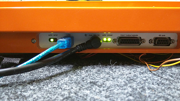 +Inside of the enclosure, the LEDs are not easily visible at the back of the enclosure. As of right now, there is no practical solution to this issue aside from opening the doors and trying to look around to see the LEDs.
+
- Attach and fasten drill head + drill machine:
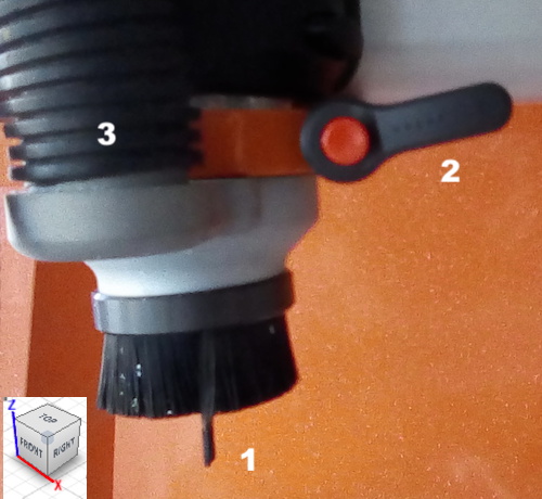
- Make sure that the right drill head is put and fixed inside the drilling machine
- Adjust and fix the milling head with the "Schnellspannhebel" (quick clamping lever)
++This is followed by turning without the button pressed and pushing it again.
++Works similar to a ratchet ("Ratsche").
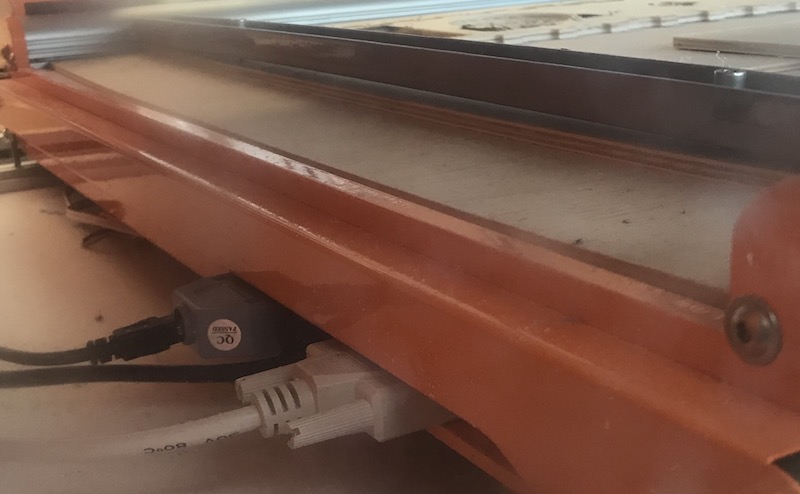
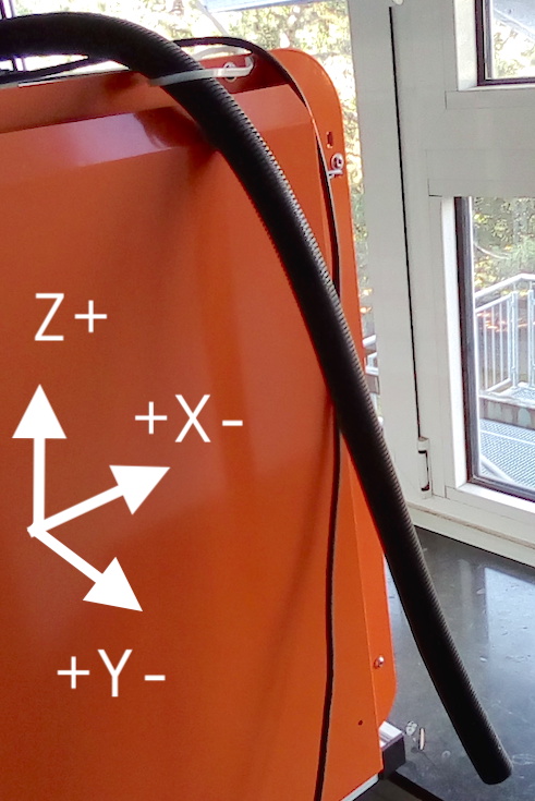
- The vacuum cleaner should be connected to the tube on Y+ side of the CNC machine (see below) and the tube of it fixed to the drill head (see 3 above)
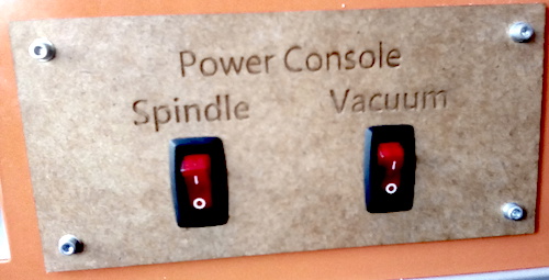
- Turn on vacuum and/or drill
Moving the CNC mill head (Go to top)
- The first thing to do is to move the arm to the zero point on the X and Y axis. It is advised that this point still leaves space of 50-70 mm to the edges.
+In UCNC, use the sidebar on the left.
- If UCNC throws the error ‘soft axis/limit reached’, press override limits, move the head to a safe position and restart the milling process.
- Make sure the path of the mill head is not obstructed by e.g. one of the tubes
+
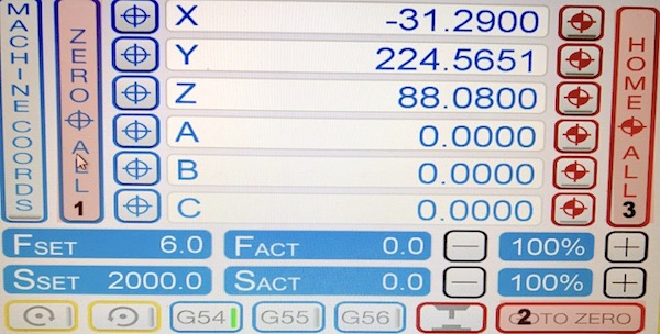
- Press ZERO ALL to save the position as zero (the origin of the gcode file).
- GO TO ZERO will tell the mill head to go to the saved position.
- If something goes wrong, the HOME ALL will send the mill head to the origin of the cutter.
AUTODESK FUSION 360 - Preparation of the 3D model / CNC mill machine path (Go to top)
To begin the milling process, we need to virtually create the model you want (re)use and mill. For this we recommend using Fusion 360 by Autodesk. The university version of this app is free to use for 2 or 3 years. Logging in with Your account gives access to all Your models in the cloud.Before and while you design your model, there are some things you need to consider, which will make milling easier and reduce the risks and chances of possible issues you might come across.
Fusion 360: Coordinate system - Axes:
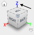
In the top right corner of the modeling space you can see the orientation of all three axes.
For modeling itself the orientation is not that important but milling machine uses a real coordination system, you should use the same orientation here as well.
This means that Z should be the axis going up and down and X and Y should define length and width.
You can set this up in preferences (top right corner, click on your account name first)
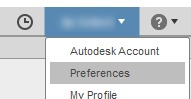
in the field Default modeling orientation and select Z up.

Fusion 360: Modelling (Go to top)

Preparation of Your 3D Model has two approaches: constructive or subtractive.
In the former, the object is constructed by means of expanding, extruding or adding elements, whereas the latter approach takes a large model and chisels or cuts unwanted parts out. Both have benefits and drawbacks.
While designing the model to be used in the milling process, one should have the tool (= milling head) in mind. This means that for example, a thick tool head can not be used to engrave a small and detailed path. Conversely, a fine tool will require a very lengthy amount of time to clear a large area.
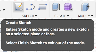
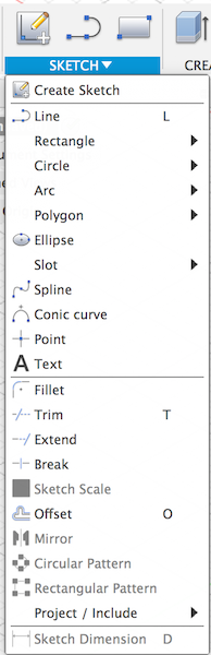
Fusion360: Model / Sketch
Sketching in Fusion360 is a way to begin the modelling process from a 2D blueprint. This menu allows for a variety of geometric shapes and tools - lines, rectangles, ellipses etc. To create a sketch, choose the appropriate menu and make sure you choose the proper working plane.
Fusion 360: Coordinate system - Working plane:
As a ground rule we advise to create your model within the positive area of the coordination system. When creating an object or a sketch, choose the X/Y plane and place it within the positive area (by default upper right and the area where the axes have numbers).


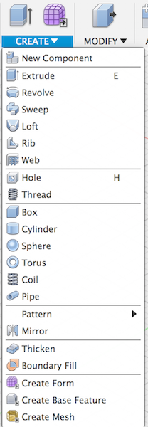
Fusion360: Model / Extrude
One of the most fundamental tools in 3D design is the extrude operation. It takes a 2D face and by copying it at a specified distance and connecting the sides, it creates a 3D structure with the face duplicated as top and bottom and a simple planar connection as the sides.
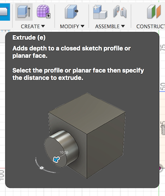
- In the first step, we need to select a face or "profile" to be the base of the 3D object.
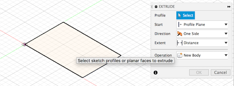
- Secondly, we should enter the height of the structure, i.e. the distance between the top and bottom plane.
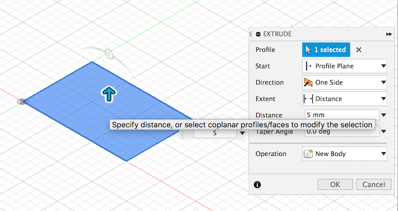 +One could also enter a negative number to press the face into the created body, i.e. subtract it.
+
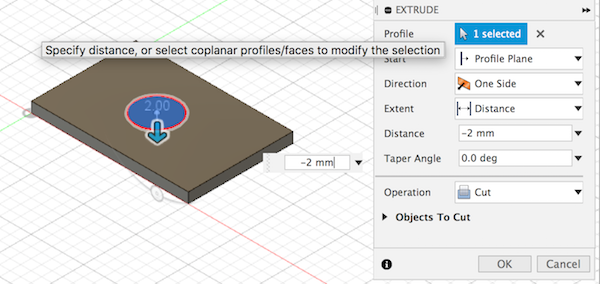
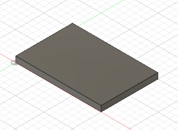
- The outcome of the operation is a 3D cube.
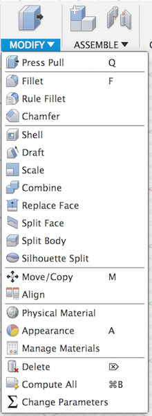
Fusion360: Modeling / Further steps
By means of a combination of the basic operations from the Sketch, Create and Modify menus, the modelling process can be expanded into more complicated structures.
Fusion360: Joints and drilling holes
In case you want to assembly or combine parts, but want to avoid using other tools or material, you can do this by using so called joints. The most common way you might already know can be seen on the picture below.
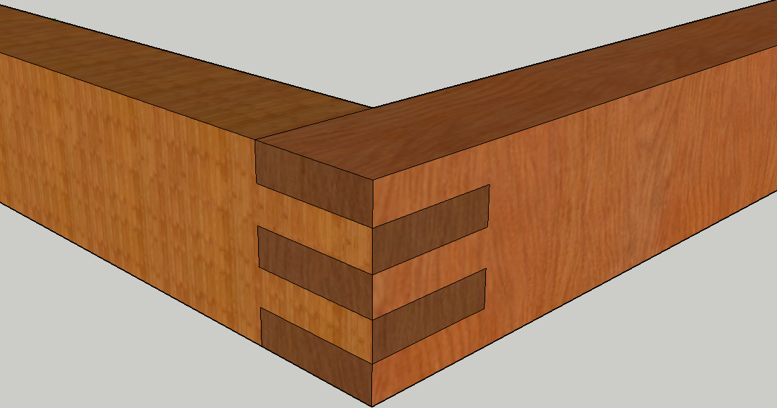
There are many ways to design joints but we need to keep in mind here, that the (default) milling head works in a round way. This means, that we cannot produce exactly edgy corners like like in this case. As an easy workaround, we recommend using drill holes. This is a feature of Fusion 360, hence you don't need to change your design. You can make the "tooth" pattern above and then make use of the drilling tool to achieve this.
Fusion360: Model / Inspect
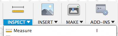
The inspect menu and more specifically, the measure tool allows to check distances or radii of the created model.
Fusion360: Model / Insert
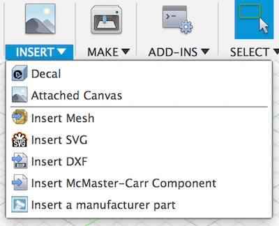
The insert menu can be used to import a variety of file format to aid the modelling process - one example could be a sketch of the design to base the design process off of it.
Fusion360: Model / Make
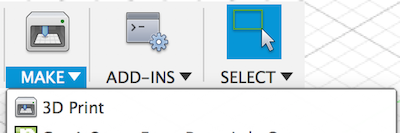
The make menu is particularly interesting in the concept of 3D printing as it provides an easy way to generate STL files and in some cases even send the file directly to a 3D printing program such as Cura.
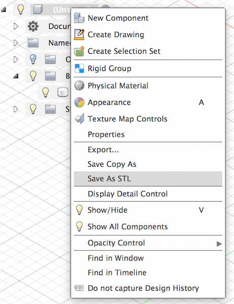
One thing to keep in mind: if the model has multiple bodies, this menu will not work. A workaround for this, is to select the project in the document overview and from there choose "Save as STL" to generate the necessary files.
Fusion 360: CAM (Go to top)
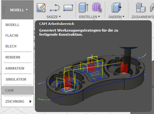
After the 3D model has been finalised in the model step, we can move to the CAM tab of Fusion360 which calculates the path of the milling head through the material.
Additionally, this mode allows to set up different methods to define the areas and sections which will be processed by the milling machine.
We now assume that you have your model loaded with the holes, contours, etc. you want to mill.
In the following we will explain how you can choose fitting operations create a setup and then generate a script which will tell the machine what to do.
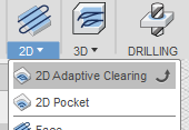
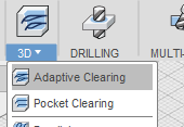
As a general approach, Fusion distinguishes between 2D and 3D milling operations.
Roughly speaking, in this context, 2D means that in all parts, the depth is constantly the same and 3D means the depth can vary.
A variety of operations can be chosen to calculate the milling path, each with their own drawbacks and benefits. Fusion360 is a very powerful tool, so not all aspects of this program will be described here. This documentation will focus on the most important strategies you can use for your tasks: (2D/3D) Adaptive Clearing, 2D Pocket, Radial. While the first two can be found at both 2D and 3D, the latter is specifically for 3D milling.
Fusion 360: CAM - Setup
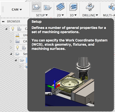
After choosing all milling operations in the steps before - choose the "Setup" option.
This is a global setting for all the operations you plan.
- Inside the 'Setup' Menu, choose the "Stock" tab.
- Remove the Stock Offset, the default 1mm is only distracting.
- Here we can also choose the Stock Point again to match the coordinate system of the model properly.
- After confirming the Setup Menu, the matching operation will have a red !.
- This can be removed by double clicking the operation and pressing OK again ;)
- Make sure Setup entry point and Operation entry point match.
Fusion 360: Tool library
Here you can see all the tools available in Fusion 360. The word "tools" here describes milling heads.Each such head has a different job - some are good for fine engraving, some are good for clearing large pockets, others have more specialised applications.
Choosing the right tool for the job is essential for an efficient milling process.
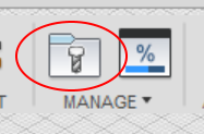
To open up the Tool Library, on the CNC tab, click the file icon with the screw
 We have created a custom Tool Library to match the milling heads which are available in the Fablab. You can download it here: Fusion360 CNC Tools v1.
Importing the tool library can be done by right clicking on Local, then choosing Import Tool Library and selecting the downloaded file.
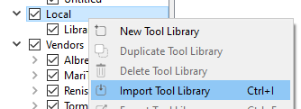
Now you should see a new library beneath Local, which contains our very own tools. For now, you can check the parameters of each tool but don’t change them! In case you accidentally do, delete the library by right-clicking it and clicking Delete Tool Library and import it again.
Fusion 360: CAM - Choice of tool
One setting which appears in every method is the selection of the tool.The tools are essentially parametrised models to describe in detail how the milling heads look like and which measurements they have.
This selection heavily influences the calculated tool path which is required to mill the chosen model.
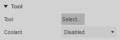 This is always done in the first tab. Click Select, which will open up the Tool Library (see Tool Library).
Open our custom library and choose the tool you want to use for this particular task.
Fusion 360: CAM - Choice of tool / Cutting Feed Rate
This setting indicates how quickly the material should be cut.This number should match the material, otherwise it could burn or melt.
Always use an insignificant spot of Your material to test before applying in production.
A good number for wood is ~ 500 mm / min.
Fusion 360: CAM - Choice of tool / Height
This setting indicates how deep the mill should cut into the material.Fusion 360: CAM - Choice of tool / Entry Point
This setting indicates where the milling head should begin the cutting operation.Fusion 360: CAM - 2D/3D Adaptive Clearing
This method is the “strategy to go” for the most simple setup. This is due to the fact that in this case, you only select the area in which you want to mill certain things, and the area is then automatically scanned to determine the best way to do this. Hence, this method also requires the least steps and parameters.
Fusion 360: CAM - 2D Pocket
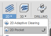
If you want to remove material but the form is not organic but has edges, you should use a pocket. This method is more reliable to ensure that edges are not rounded, which is a downside of adaptive clearing.
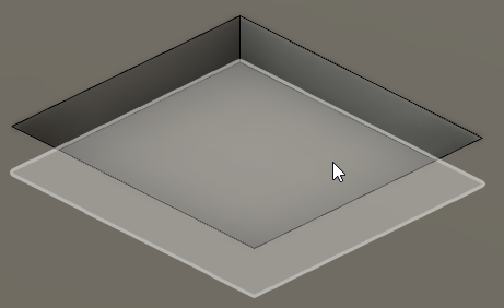
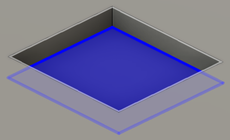
In the first tab all you need to do is select the tool. In the second tab, click on the Nothing button and then select the bottom of the area which needs to be milled. It should look like on the first picture when selecting it and the second picture shows what it looks like when it's confirmed.
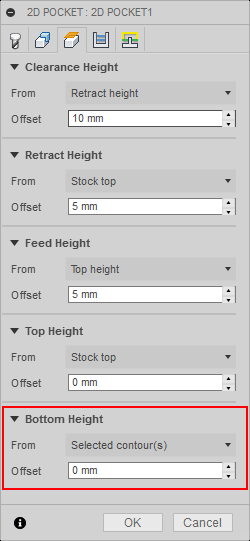
Now in the third tab Heights we only need to change the Bottom Height. Click on Selected contour(s) (or whatever From is set to) and click Selection.
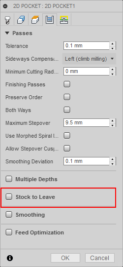
In the fourth tab, leave everything except Stock to Leave. Per default this option is enabled, but we need to deactivate it as it is not needed.
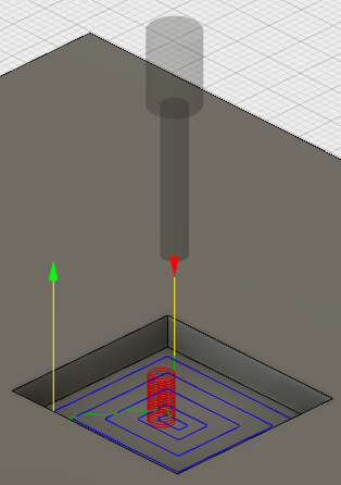
The fifth tab can be left as is, therefore just confirm by clicking OK. Afterwards Fusion will generate a so called tool-path, which, as the name suggests, is a computed pathway with regards to the to the chosen tool and method. It should look similar to the picture below. The red arrow shows the initial starting point and the green arrow shows the end position. The blue paths show the moving of the milling arm, the red spiral signifies where the mill head will drill downwards to enter the material, and the little green paths indicate a shift to the next blue path.
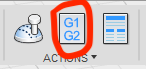
Fusion 360: CAM - Simulation
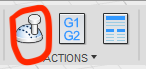
Once the entire system is set up, the model is ready and the tool path has been generated properly, we can simulate the path of the milling head through the material and see if everything is in proper order.
For this, choose the "simulate" option from the Actions group in the CAM tab.
The green bar at the bottom of the window signifies the time line of the project.
A red bar shows collisions.
Activating the "Stock" tab allows to see what's actually happening.
Using the 'ceramic' setting is most helpful as this is the most clear visualisation.
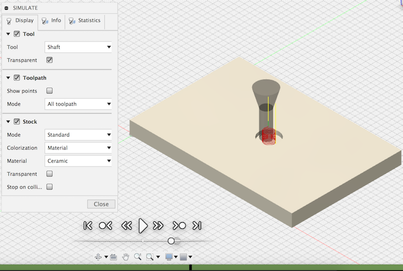
Fusion 360: CAM - G1/G2 (Post process)
In order to send the generated tool path to UCCNC, we need to post process it first. This will generate the machine code.
To obtain a postprocessor, we need to download it from the autodesk website.
- We need to browse to cam.autodesk.com, search for 'stepcraft' and choose "UCCNC".
- Download this file into /Users/{$CURR_USER}/Autodesk/Fusion 360 CAM/Posts
- Restart Fusion (possibly not necessary)
- Choose "Personal POSTs" in the post process window
- Locate the file we just downloaded
- The Program Number field is useless as you will be asked to specify a location and filename anyway
- The Program Comment field will appear in the generated code at the beginning
- This will generate a *.nc file.
Loading the compiled gcode into UCCNC (Go to top)
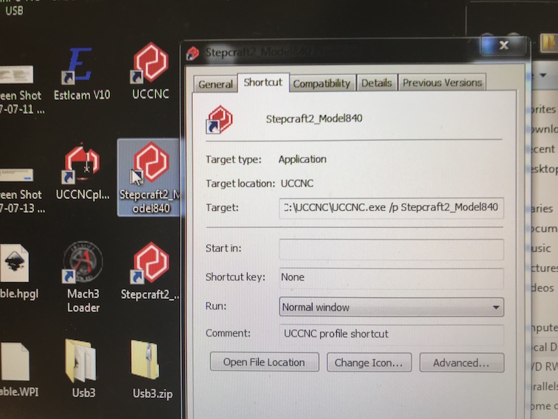
The control software (UCCNC) is only available via windows - use parallels- Use the shortcut on the desktop to start UCCNC.
 +
+
- The “reset” button in UCCNC will blink, click it,
 +Locate the reset button on the machine and press it (to check).
+

- Load *.nc file
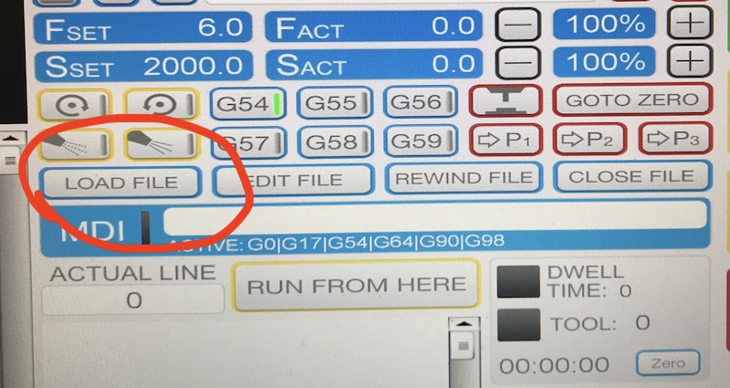
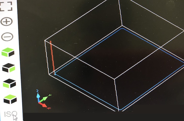
- After loading, UCCNC shows the preview and a coordinate system
+The red rod represents the tool (milling head), the blue is the tool path and the white bounds represent the bounds of the overall structure to be milled.
+
After loading the file - milling process (Go to top)
- Make sure the machine is on and prepared correctly
- Home all
- Move head to the starting location
- Zero all/zero axis = set milling origin to current head position
- Adjust Z s.t. drill head touches the material
DEVICE TECHNICAL INFO (Go to top)
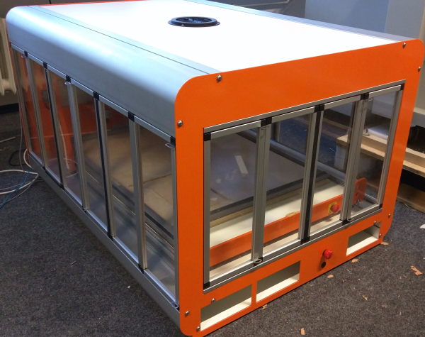
Full name: Stepcraft D-840
Enclosure and Sizes
| Axis | Size Bed | Size Enclosure |
|---|---|---|
| x | 60 | 70 |
| y | 50 | 120 |
| z | ~10-15 | 80 |
Material
In general, the mill can work with a few materials - for example wood, aluminium or styrofoam.Milling heads
Status: Awaiting discussion
The following list contains milling heads we could order and use for our stepcraft. However, as far as I understand, these are only for wood. But I can look into it in more detail when this is discussed.
| Diameter | Max. milling depth | Shaft | |
|---|---|---|---|
| T-TR01X8MMTC | 3.2 mm | 12.7 mm | 8 mm |
| TI-M310-70-8 | 3 mm | 10 mm | 8 mm |
| KLE-T162-030-R | 3 mm | 12 mm | 8 mm |
| TI-M2-58-8 | 2.5 mm | 8 mm | 8 mm |
| T-2-08XMMTC | 1 mm | 3 mm | 8 mm |
| T-3-06X8MMTC | 2 mm | 5 mm | 8 mm |
| E-10352 | 3 mm | 8 mm | 8 mm |
| TI-M410-70-8 | 4 mm | 10 mm | 8 mm |
| E-10350 | 2 mm | 6 mm | 8 mm |
| T-C001AX8MMTC | 3 mm | 9.5 mm | 8 mm |
| T-DH-01X8MMTC | 1.6 mm | 5 mm | 8 mm |
| T-DH-02X8MMTC | 2 mm | 5 mm | 8 mm |
| T-3-1X8MMTC | 5 mm | 16 mm | 8 mm |
| E-10354 | 4 mm | 12 mm | 8 mm |
| E-10358 | 5 mm | 20 mm | 8 mm |
| T-3-3X8MMTC | 7 mm | 19 mm | 8 mm |
| E-10950 | 6 mm | 20 mm | 8 mm |
| E-10042 | 3 mm | 12.7 mm | 8 mm |