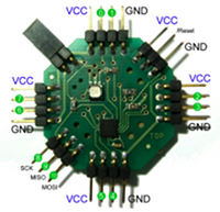
LumiNet
Pin mapping

This page describes the LumiNet I/O pins. It should help to understand the mapping between API pins (pin 0-19), the attiny pin names, and the analog input pins.
LEDs and Reset
The LED can be used if the jumper on the top left side of the board is closed. If the jumper is open, the three pins on the bottom left side of the board can be used instead of the LED. The mapping is:
red led: PA4 (d8) - SCK
green led: PA5 (d9) - MISO
blue led: PA6 (d10) - MOSI
Please note, that the LED pins can also be used for analog input (because they are pins of PORTA).
The reset pin is located on the top right side of the board.
reset: PB3 (d11)
Digital Pins
Use the pin-numbers 0-19 for digitalRead() and digitalWrite(). The following table shows the pin-mapping for these two functions:
| digital Pin | attiny pin name |
|---|---|
| 0 | PA7 |
| 1 | PB2 |
| 2 | PB1 |
| 3 | PB0 |
| 4 | PA0 |
| 5 | PA1 |
| 6 | PA2 |
| 7 | PA3 |
| 8 | PA4 |
| 9 | PA5 |
| 10 | PA6 |
| 11 | PB3 |
| 12 | PA4 |
| 13 | PA6 |
| 14 | PA0 |
| 15 | PA1 |
| 16 | PA2 |
| 17 | PA3 |
| 18 | PA4 |
| 19 | PA5 |
The numbers 0-10 can be seen in the picture on the top of this page.
The highlighted pins can be used for analog input. But in the case of analog input, not the digital pin number must be used, but the PAn number. Example: you want to read an analog value from pin 10, then use: analogRead(5). The next section explains analog input in more detail.
Analog Pins
All pins or PORTA can be used for analogRead().
analogRead(0) reads pin PA0. Look up PA0 in the table above and connect the sensor to the corresponding pin (in this case: use pin "5" of the LumiNet board).
Use the digital pin numbers (0-19, see table above) for digitalRead() and digitalWrite(), but only use the PAn numbers with n=0..7 for the analogRead(n) function.
On LumiNet, analogWrite() doesn't use hardware PWM, but the Bynase protocol. analogWrite() is available for all pins. Use the same numbering as for digitalWrite().

