FabScan - Assembly Instructions
For more information about the FabScan visit the project site.
These assembly instructions are work in progress. Expect the files and instructions to change.
Preparation
(These are the most up-to-date files available)First download and lasercut all the parts.
The estimated time it takes on a Zing6030 lasercutter is indicated for each file:
1a. Turntable-, camera- and laser-holders (Quickcam 9000 Pro) .cdr .svg .plf 18:31 min
1b. Turntable-, camera- and laser-holders (Logitech c920) .cdr CamLaserTurnTableHolderFinal c920.svg .plf 18:31 min
2. TurnTable, Middle-plane and Cover Top Side .cdr .svg .plf 11:14 min
3. Cover Bottom and Front Side BoxBottomFrontFinal.cdr BoxBottomFrontFinal.svg BoxBottomFrontFinal.plf 18:30 min
4. Cover Back Side and Slope.cdr .svg BoxBackPenteFinal.plf 12:27 min
5. Cover Left Side .cdr .svg BoxLeftSideFinal.plf 06:21 min
6. Cover Right Side .cdr .svg BoxRightSideFinal.plf 06:57 min
Also 3D-print these files:
1. TurnTable Holder .stl .scad 2. Laser Holder .stl .scad
These are the eagle files for the PCB:
PololuTestShield.brd PololuTestShield.sch
Important Notes
- Most laser cutter parts are labeled with letters. When assembling, these letters indicate the corners that belong together. After the assembly, the letters should be visible, so do not try to hide them.
- The .plf file format might be new to you: it stands for "Portable Lasercutter Format". Click here for more information.
Turntable Holder
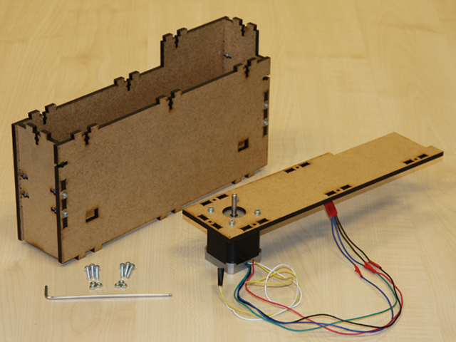
These are the parts that you need to assemble the turntable holder: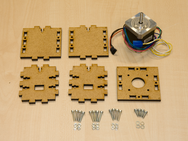
Parts List for the Turntable Holder
- All the MDF parts labeled with a C
- 4x M3x10mm Screws
- 4x M3 Washers
- 12x M3x16mm Screws
- 12x M3 Nuts
First attach the stepper motor to the top part using the M3x10mm screws. Do not forget the four washers. Then put together the four sides of the holder. If you think it is stable enough you might omit the screws.
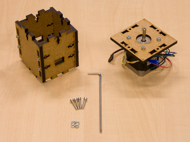
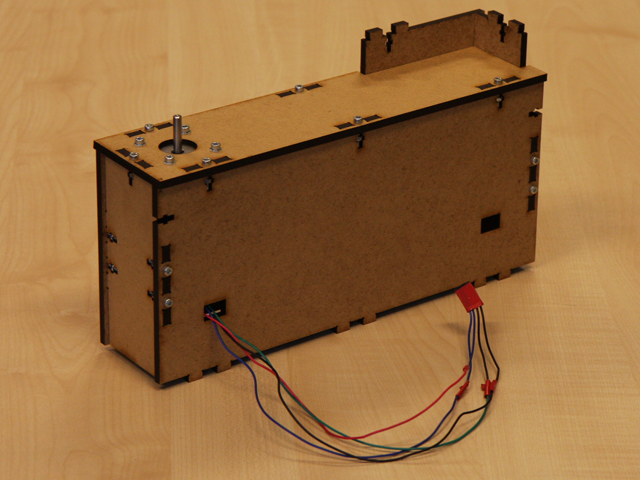
Now the final steps: first plug the four used cables of the stepper motor through one of the holes of the bottom part. Since it is symmetric, you can just pick one hole.
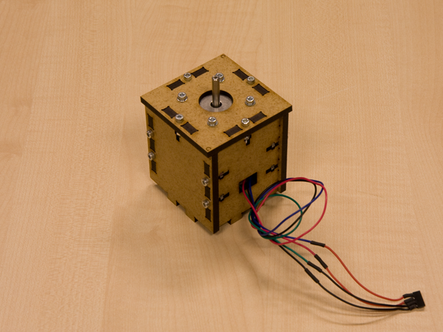
Then put the parts together, fix the screws and you are done:
Camera and Laser Holder
These are the parts that you need to assemble the camera and laser holder: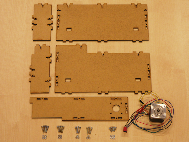
Parts List for the Camera and Laser Holder
- All the MDF parts labeled with a A and B
- 4x M3x10mm Screws
- 4x M3 Washers
- 14x M3x16mm Screws
- 14x M3 Nuts
Again, fix the stepper motor with the 10mm screws and the washers. Make sure the engine is rotated correctly, otherwise the cables might be to short. Put together the corners that are labeled with A and B. Finally put those two parts together like shown in the picture beolow:
Then put together the two parts and put the cables from the stepper engine throw the hole.
Camera Holder
These are the parts that you need to assemble the camera holder: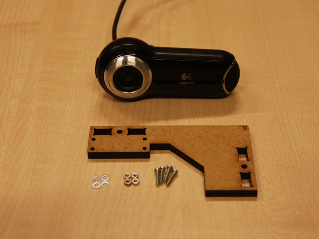
Parts List for the Camera Holder
- Logitech Quickcam Pro 9000
- The MDF part labeled with B
- 4x M2x10mm Screws
- 4x M2 Washers
- 4x M2 Nuts
Remove the original Logitech holder from the camera, and attach the MDF holder like shown in the two pictures below:
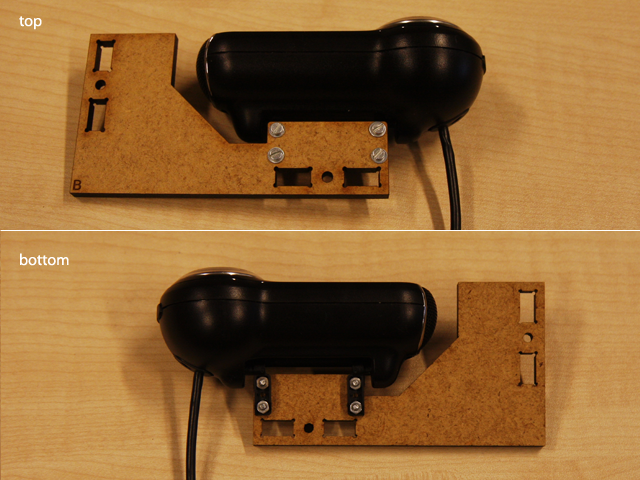
Finally attach the camera holder to the base and fix it with two screws and nuts.
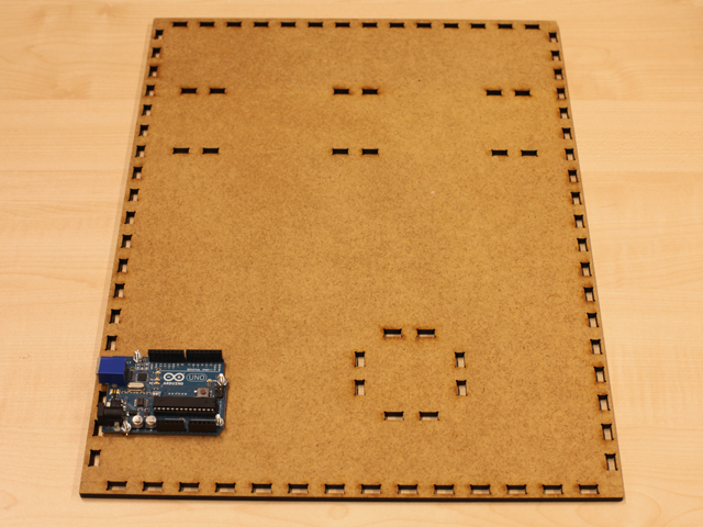
Bottom Plane and Arduino
These are the parts that you need to assemble the Arduino to the bottom plane: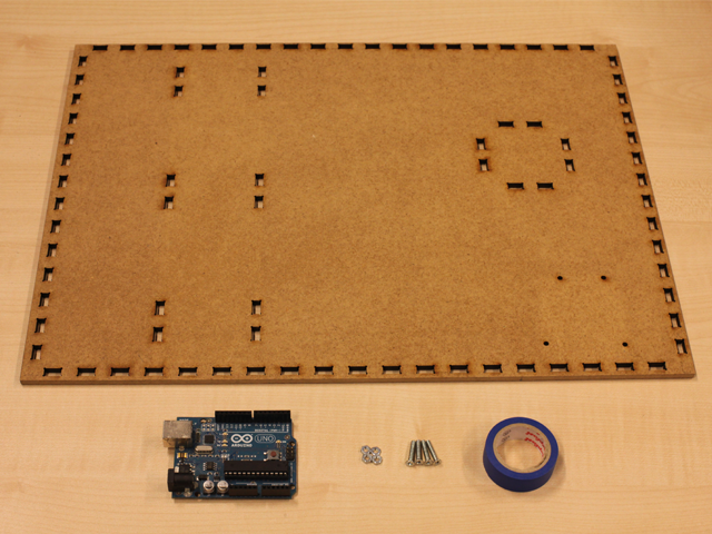
Parts List
- 4x M3 Screws with cone shaped heads
- 4x M3 Nuts
- 1x Arduino Uni
- Cover-Bottom-Plane MDF Part
- Insulating tape
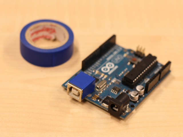
First put some insulating tape on the USB socket of the Arduino.
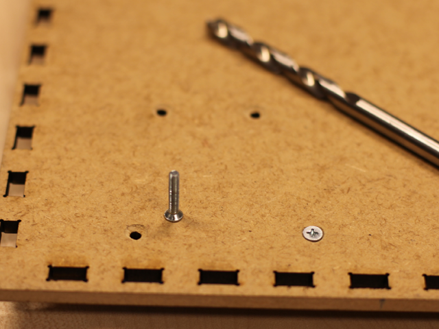
The bottom of the scanner housing should be flat, so no screws should stand out. Use a drilling bit to make the opening a little wider on the bottom side of the MDF part, like shown in the picture.
Then attach the Arduino with the 4 screws.
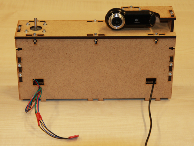
FabScan Cover
Take all the laser-cutted parts for the cover and assemble them as shown below:
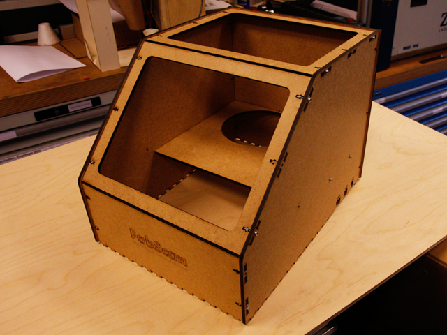
Take care not to mix up the "slope side" and the "top side". For the back side, make sure the rasterized line points to the inside of the box. This line indicates the zero position of the laser line. Make sure the laser line points there before you start a scan!
Turntable and LaserHolder
Just print the parts, attach the turntable with 4 screws and put the laser inside the holder.The vertical alignment of the laser can be checked when everything is mounted. The laser line is focused by turning at the back part of the laser. When doing so, disconnect the laser wires from the board otherwise they get twisted.
Connecting PCB
First put a socket on both stepper motors wires. Connect the wire like shown in the picture. The yellow and white ones are not needed.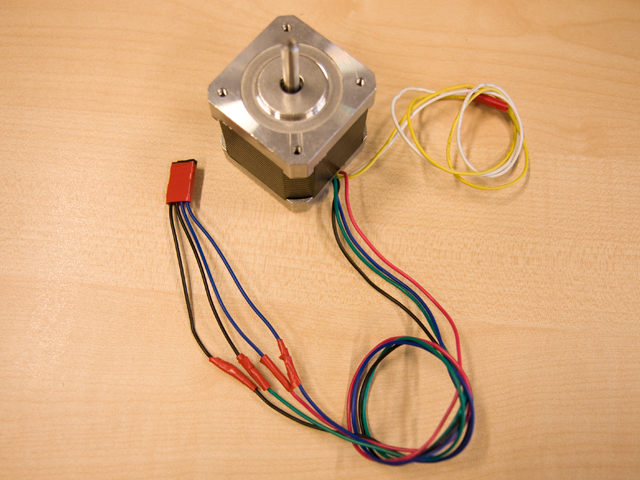
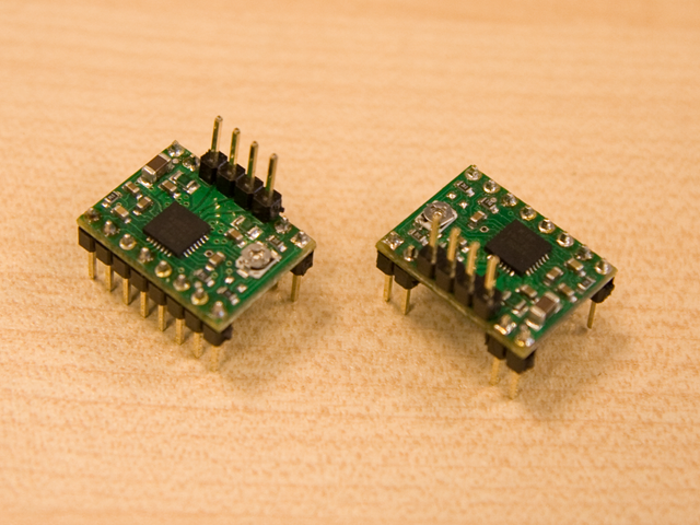
Solder connectors to both Pololu Stepper Motor Drivers as shown in the picture bellow. The ones to the top are used to attach the stepper motors.
Soldering PCB
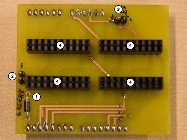
Number 1 is diode N4001. Take care of the correct polarization.Number 2 is the connector for the laser. (- is top, + is bottom)
Number 3 is the connector for the white LEDs. (- is right, + is left)
Number 4 are the sockets for the Pololus.
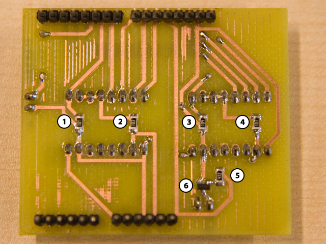
Number 1 is a 100k Ohm resistor.
Number 2 is a 10k Ohm resistor.
Number 3 is a 100k Ohm resistor.
Number 4 is a 10k Ohm resistor.
Number 5 is a 4,7k Ohm resistor.
Number 6 is a BC 847C transistor.
LEDs
Later we will put a cover over the whole setup. To illuminate the inside, we put 3 LEDs.In front of every LED solder a 180 Ohm resistor. With some wires we attach it to the socket on the PCB.
Final Steps...
Place the Laser- and Camera Holder as well as the Turntable holder onto the bottom plane. Put the laser as well as the turn table onto the steppers. Attach the wires of the steppers to the Arduino as shown in the picture. Use some adhesive tape to attach the LEDs just below the camera.
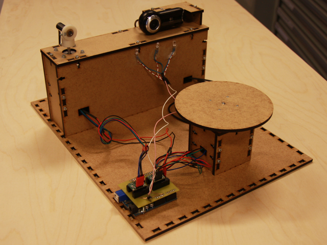
now just put the cover on it ...
..and you are done!