CNC Mill Tutorial for the SRM-20
Initial Setup
This part is about basic computer and machine handling for using the SRM-20 in the Fab Lab.
Computer handling
All programs that are needed to operate the SRM-20 are installed on the Mac which is labeled with "SRM-20". As the programs run on Windows, there is a Windows partition on the Mac. To access this partition you have to press and hold the "options"-button (last row, third key from the left) on the keyboard while the Mac is booting. Select the first Windows-partition from the left. All programs are put on the desktop.
Machine handling
Please make sure, that the machine is clean before you use it. If this ist not the case, use a vacuum to clean it. Please clean the machine after you have finished working with it.
Connection
Make sure that the machine is connected to the Mac and is plugged in.
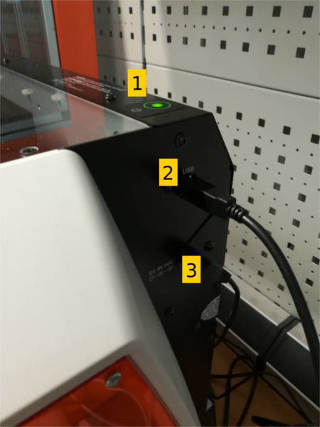
- On/Off button. It glows green, when the machine is running
- Cable that has to be connected to one USB port of the Mac
- Power supply
Mill usage
Working plate
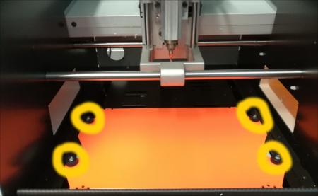
Remove the working plate
If needed, the working plate can be removed from the machine. Follow these steps:
- Center the spindle head
- Open the cover of the machine
- Unscrew the 4 screws that hold the working plate. You can use your hands for that. There is no need to unscrew them completely, just make them loose
- Take out the working plate by pulling it towards you and then lifting it. Do not tear it, if it is stuck!
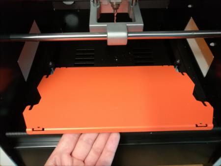
- Make sure to screw the 4 screws tight again, when you put the plate back to it's place
Attach material to the working plate
- Center the spindle head
- Mark the origin of the material with a pencil. This mark helps you to align the tool properly later
- Put double sided tape on other side of the material
- Attach the material to the working plate. Put the material as far to the front as possible
Cutting tools
Currently the Fab Lab only provides a 3mm drill, that is already fixed in the machine.
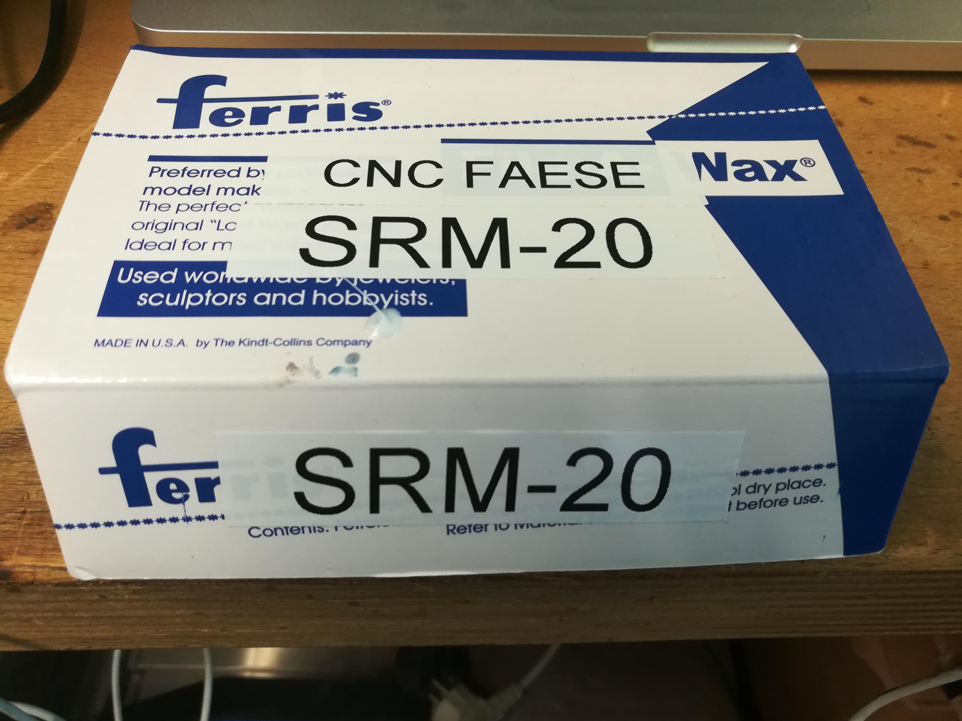
Other tools to change the cutting tool (e.g. spanners) are placed in a box labeled "SRM-20" which is placed in the shelf above the machine:
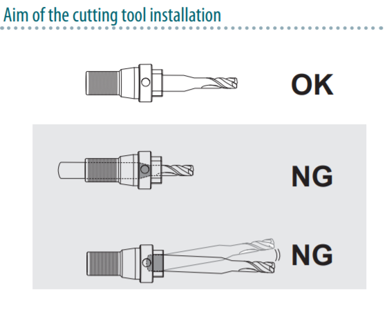
Make sure that the drill is in a position according to the following:
Center the spindle head
- Close the cover of the machine
- Open VPanel

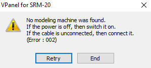
If you receive the following error message make sure to follow the connection instructions and press "Retry":
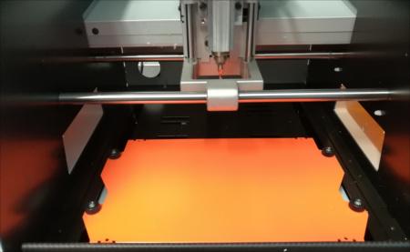
- Click on "View" in the bottom row.
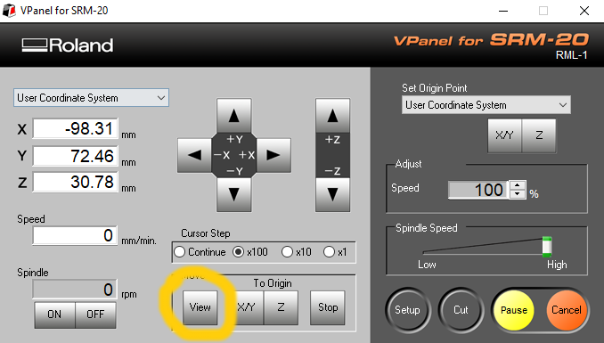
This brings the plate to the front and lifts the tool
Install a cutting tool
If the cutting tool is not in the machine do the following:
- Center the spindle head
- Open the cover of the machine
- Insert the cutting tool, and then loosely tighten it
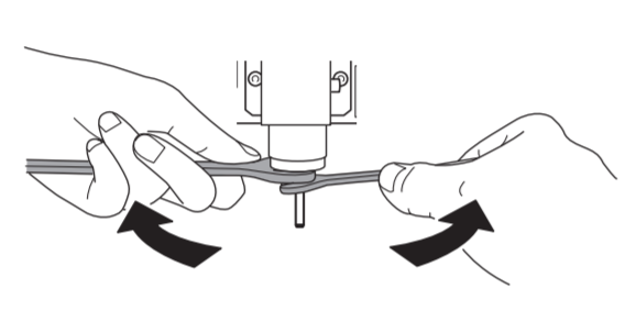
- Secure that the cutting tool is tight by using two spanners
Remove a cutting tool
To remove the cutting tool do the following:
- Center the spindle head
- Open the cover of the machine
- Make the cutting tool loose using two spanners
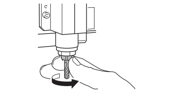
- Remove the cutting tool with your hand. You may need to unscrew it a little bit
Create a cutting file using MODELA Player 4
To create a file that is executable by the SRM-20 you can just follow the step by step instructions from the manuals:
- Complete manual and documentation (external): starting at page 51
- Complete manual and documentation german (internal): starting at page 33
If you already know what to do in the steps you can follow this overview:
- Open the stl file using MODELA Player 4
- Set the Machine Selection
- Model Name: SRM-20
- Comannd Set: RML-1
- Spindle Unit: Standard
- Printer Name: Roland SRM-20
- Set the origin point of the model and orientation
- Click the model icon

- Select "Origin"
- Choose your settings
- Click the model icon
- Set the size of the cutting data
- Click the model icon
- Select "Size and Orientation"
- Choose your settings
- Click the model icon
- Select the material you are using
- Set the margin
- Create the surface leveling process
- Tool: 3mm Square
- Create the roughing process
- Tool: 3mm Square
- Create the finishing process
- Tool: 3mm Square
- Save the created cutting file
Set the origin of the tool
- Close the cover of the machine
- Open VPanel
If you receive the following error message make sure to follow the connection instructions and press "Retry":
- Select "Machine Coordinate System" in the left upper corner
- Click on "X/Y" and "Z" in the middle on the bottom
- Check that all coordinates are set to 0.00
- Select "User Coordinate System" in the left upper corner
- Use the x and y arrows to align the tool with your marked point on the material
- Use the z arrows to place the tool slightly above the material
- Loosen the set screw, so it contacts the surface of the material
- Tighten the set screw again
- Click on "X/Y" and "Z" on the right under "Set Origin Point"
- Accept the new origin in the program
- Make sure that all coordinates show 0.00 again
Cutting process (one sided cutting)
To perform cutting on the SRM-20 you can just follow the step by step instructions from the manuals:
- Complete manual and documentation (external): starting at page 88
- Complete manual and documentation german (internal): starting at page 70
If you already know what to do in the steps you can follow this overview:
- Center the spindle head
- Attach material to the working plate
- Set the origin of the tool
- Perform cutting
- Remove processed material
- Center the spindle head
- Turn the power off
- Empty the material drawer and clean the machine