PCB Milling Tutorial for the LPKF S62
- +# Important Notes
- +# Initial setup
- +# Copying your files.
- +#Processing the Eagle files
- +# CircuitCAM preprocessing
- +# Milling with BoardMaster
- +#Advanced uses
- +# FAQ
- +# Error listing
+# Important Notes
- To avoid connection errors, first open the Parallels session on the Mac, then turn on the mill.
- If something unexpected happens, just open the mill cover to stop the mill. Ask a Fab Lab Administrator for help.
- Take precautions to not spread and inhale the white milling dust. It's not healthy to inhale, and can stain clothing. Use the vacuum to remove the dust from the milling area before you turn off the mill.
+# Initial setup
You currently need to log on to the PCB milling Mac using the Fab Lab Administrator Mac account. Ask Jan Thar or Ceyda to log you in.- Launch Parallels Desktop
Launch it using the icon in the dock, and click Windows XP to start the virtual machine.
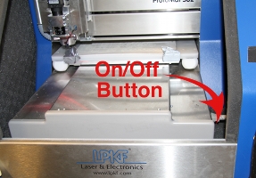
- Turn on the CNC mill
Open the plastic cover all the way so it stays up. The switch is hidden inside the mill on the right side of the bottom plate, above the power plug near the front. See photo.
Close the plastic cover of the mill before going to the next step! If you do not, BoardMaster will give errors, and you will have to close BoardMaster, close the cover and relaunch it.
- Launch BoardMaster
The shortcut is on the desktop.

If you get a connection error:
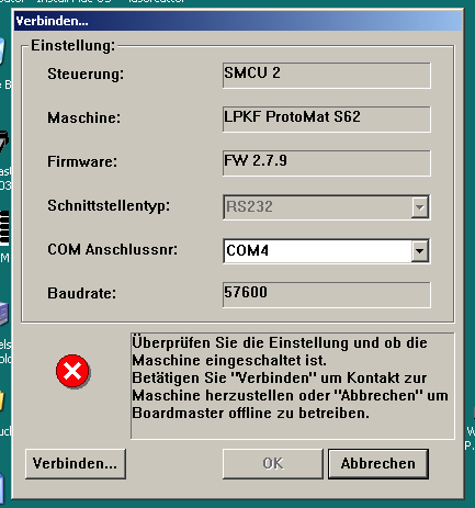
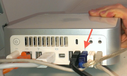
Keep clicking OK until all dialogs are gone, close BoardMaster, unplug and replug the blue USB plug from the Mac on the shelf above the mill.
When it asks where to connect the USB device, select Windows XP. Then relaunch BoardMaster.
When you get the error below, check for the tool in milling head
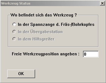
When opening BoardMaster, you will get a "Werkzeug Status" dialog asking if there is a tool in the milling head.
Check if there is a tool in the head. Look through the front gap in the milling head where the blue/white light is. There should be no drill or other tool there. You have to bend down a bit to look through the gap. (see photo).
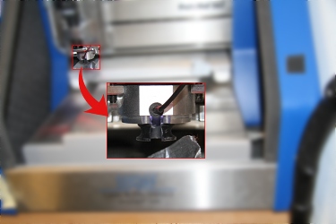 -Milling head without tool-
If there is no tool, just press OK.
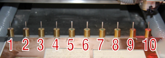
If there is a tool, check the first radio button. Look to the right of the milling head: All the way at the back of the mill you can see the ten tools lined up. One of them should be missing. Type the number of that tool into the dialog box (1 to 10 counting from left to right), and click OK. It will ask if you want to return the tool to the tool placeholder. Click Yes. The mill will put the tool back.
- Park head and check camera
After BoardMaster has launched, press the blue "P" toolbar button . The head moves to the parking position, and you can see that movement in the onscreen camera window.
To double-check if the camera is working, you can also wave your finger under the camera and see if that appears in the onscreen camera window.
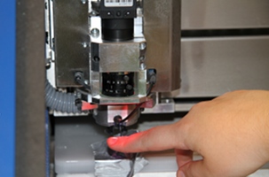
If the camera does not work: Close BoardMaster, then unplug and replug the black USB plug from the Mac on the shelf above the mill (see picture at point 3). When it asks where to connect the USB device, select Windows XP. Then relaunch BoardMaster.
- Load PCB material.
Find a used piece of PCB material. Do not use a new sheet until you have proven that your design fits on none of the existing used PCBs. Don't waste material.
Check that the PCB material you picked is covered with copper single-sided or double-sided, depending on what you need for your board!
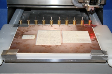
For new material, check if the two holes are big enough for the pins. If not: slightly widen the pin holes on the PCB with one of the 5 black screwdrivers with the red head (their diameter is 3mm). Otherwise the pin may get stuck. (Re-check these instructions).
Put the two locking pins into the PCB and tape down the PCB with duct tape at all four corners (see photo).
- Iconify (minimize) BoardMaster, don't close it.
+# Copying your files.
- Open the folder "Mill" on the desktop.

- Locate (or create if it's not there) a folder with your full first and last name (e.g., "Jane Doe") inside Mill Users.
- Create a project folder with the current date and a meaningful name of your project inside your user folder (e.g., "110923 My Cool Gizmo v1").
+#Processing the Eagle files
Usually, you should have done this in Eagle at your computer already (see mill). If you haven't, you can do it in Eagle on the milling Mac:
- Open the .brd and .sch files in Eagle
- Press the "CAM-Prozessor" button
 to generate the GERBER files
In the dialog select the "Datei" menu and from the "Zuletzt geöffnet" submenu click the the "C:/Program Files/EAGLE-5.7.0/cam/LPKF_2Layer.CAM"
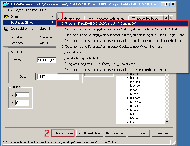
Then press "Job ausführen", and wait until the blue progress bar disappears (or untill you realize it is not thinking anymore, the window will not close by itself).
The following files will be generated:
- .BOA (board outline)
- .BOT (bottom)
- .DRD (drill data)
- .TOP (top)
- Copy these four files of your project (BOA, BOT, DRD, TOP) into your new project folder in the Mill folder.
- Close Eagle
+# CircuitCAM preprocessing
- Launching CircuitCAM
The shortcut for CircuitCAM can be found on the Desktop.

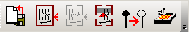
All you use in CircuitCAM is the four big buttons near the top left.
- Importing your files
Press first button: "Importieren"

Select all your four files (.BOA, .BOT, .DRD and .TOP), click "Open" - Creating the outline
Deselect TopLayer, BottomLayer, DrillPlated by clicking on the tiny green checkmarks in front of them.
Select your outline by dragging with the mouse
Press second button: "Konturgenerator"

In the dialog, press "Starten" (not "OK"!)
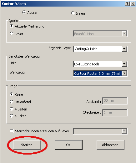
Your board outline gets a nice fat yellow border.
Re-enable the layers you deactivated before (at least TopLayer, BottomLayer, DrillPlated).
- Creating a bridge
To prevent the board from damage while cutting the outline, you should insert some bridges so it stays in its position.
To insert a bridge click the outline

and use + and - to select the desired position and press the Bridge Button to insert the bridge.
- Marking places for rubout
Rubout means it will remove copper in selected areas of the PCB. It is usually used for SMD components in order to make soldering easier (see picture).
When rubout is not used, the mill only separates the circuit traces from the rest of the copper surface by engraving the contour lines as seen in the picture below.
Press Button 4: "Rubout aller Layer".

Draw squares with the mouse anywhere you want to remove (rubout) all unnecessary copper. Note: this will take a lot more time when milling.
- Isolating the layers
Press Button 5: "Isolieren aller Layer".

This draws the path of the milling tool into your board.
- Exporting the board design to BoardMaster
Press the last button to the right: "Exportieren LMD Datei".

In the dialog, you can save the CAM and LMD files (put them in the same folder as before), but you don't have to - the data gets passed on automatically to BoardMaster behind the scenes. - Close CircuitCAM
+# Milling with BoardMaster
Switch to BoardMaster in the Windows taskbar. You should see your PCB on the milling bed in BoardMaster.
In BoardMaster, click the four-arrow button
 . Then click and drag the mouse to where the top-left corner of your board should go. Don't let go while dragging, or you have to select it again. To move the head in smaller steps use the Buttons shown below (Change the number to use smaller steps).

Please position your board as close to the edges as possible, so you don't waste unnecessary material, and so others can still use the PCB sheet for their designs after you. Just check that the black plastic ring (height sensor) around the milling head won't run over any of the two locking pins in the PCB, and that the milling head won't run over the duct tape.
You can "see" where the milling head is positioned by selecting "Verfahre nach -> Kamera -> Kopf" from the menu. Remember to revert this afterwards by selecting "Verfahre nach -> Kopf -> Kamera" (screenshot?).
Click the crazy yellow pseudo 3D block toolbar button
 click and drag your board to move it where the milling head is. Don't let go while dragging, or you have to select it again.
+#Important (Read before milling)!!!
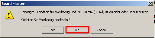
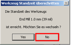
- If a dialog appears telling you that a tool is worn out ("Benötigte Standzeit für Werkzeug ... überschritten - Wechseln?"), just click No - we use the tools until they break.
- If a small PCB gets sucked upwards into the milling head, you have to remove it before you continue milling, or you will break the mill. Just click the red "VAC" button
 to turn off the vacuum pump, and it will fall back down, or you can pry it out of the head with tweezers. A better idea would be to use bridges for small parts (see below).
- Don't leave the mill while it's running. If something happens, open the transparent door, and the mill will stop immediately.
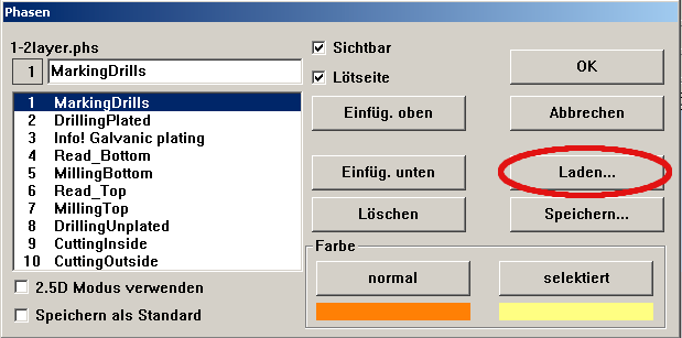
- Select "Konfiguration -> Phasen"
- Press the Load button ("Laden") and select the configuration file "SingleSidedTOPLayerSMD.phs".
- Now we step the mill through its phases. For each Phase once it's finished, you get a confirmation box showing the duration of the mill. Click OK.
Don't leave the mill while it's running. If something happens, open the transparent door, and the mill will stop immediately.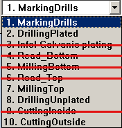
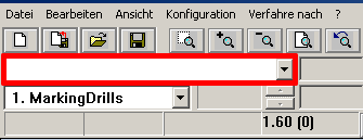
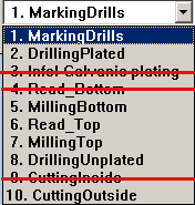
- Milling Phase 1: MarkingDrills - click All+, then Start - this makes tiny marks where the drill will go (so that it doesn't slip when drilling). It also drills Fiducials if you added them (see section about double sided boards). If you don't have holes or traces of a particular kind, you can skip this phase; it won't do anything.
- Milling Phase 2: DrillingPlated - click All+, then Start - drills vias and holes - everything that would connect through, i.e., that would get covered in conductive paste when doing manual vias with the mill. Note: If you place a "hole" in Eagle, it will end up here by default as well. Remember that your parts are on the top layer, so the copper for the holes is also on the top layer. This means: through-hole components will be on the bottom side and their legs stick out to the top layer.
- Milling Phase 7: MillingTop - click All+, then Start - this mills the traces on the top of your single-sided board
- Milling Phase 8: DrillingUnplated - click All+, then Start - if you have holes that should not be conductive (like for screws).
- Milling Phase 10: CuttingOutside - click All+, then Start - finally, this cuts the board outline out of the PCB material.
- Select "Konfiguration -> Phasen"
- Press the Load button ("Laden") and select the configuration file "SingleSidedBOTTOMLayerTHP.phs".
-
Now we step the mill through its phases. For each Phase once it's finished, you get a confirmation box showing the duration of the mill. Click OK.
Don't leave the mill while it's running. If something happens, open the transparent door, and the mill will stop immediately. - Milling Phase 1: MarkingDrills - click All+, then Start - this makes tiny marks where the drill will go (so that it doesn't slip when drilling). It also drills Fiducials if you added them (see section about double sided boards). If you don't have holes or traces of a particular kind, you can skip this phase; it won't do anything.
- Milling Phase 2: DrillingPlated - click All+, then Start - drills vias and holes - everything that would connect through, i.e., that would get covered in conductive paste when doing manual vias with the mill. Note: If you place a "hole" in Eagle, it will end up here by default as well.
- Milling Phase 7: MillingBOTTOM - click All+, then Start - this mills the traces on the bottom of your single-sided board
- Milling Phase 8: DrillingUnplated - click All+, then Start - if you have holes that should not be conductive (like for screws).
- Milling Phase 10: CuttingOutside - click All+, then Start - finally, this cuts the board outline out of the PCB material.
- Select "Konfiguration -> Phasen"
- Press the Load button ("Laden") and select the configuration file "DoubleSidedPhaseSettings.phs".
- Select "Datei-> Importieren -> LMD oder LPR..." and select the "Fiducial.LMD" file. A red dot will apear on the work area.
- Right click on the red dot and you will get the following dialog:
- Under Nutzen for the fiducials (Fiducial.LMD should be selected in the list)fill in 2 and 2 to create a rectangle
- Under Abstand fill in values close to the size of your PCB but making sure you leave a couple of milimeters from the outline of your board, the fiducials should not overlap the board. Then press ok.
- Then move the fiducials around your board with the same procedure as used when positioning your board.
- Milling Phase 1: MarkingDrills - click All+, then Start - this drills Fiducials for double-sided boards. It also makes tiny marks where the drill will go (so that it doesn't slip when drilling).
- Milling Phase 2: DrillingPlated - click All+, then Start - drills vias and through-hole holes - everything that would connect through, i.e., that would get covered in conductive paste when doing manual vias with the mill. Note: If you place a "hole" in Eagle, it will end up here by default as well.
- Milling Phase 5: MillingBottom - click All+, then Start - this mills the traces on the bottom of your double-sided board.
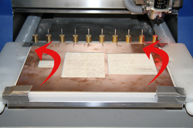
- When Phase 5 is done click the red "VAC" button to turn off the vacuum pump and park the head .
- Flip the plate away from yourself as shown in the picture below.
- Milling Phase 6: ReadTop - click All+, then Start - this recognizes the fiducials and pozitions the traces on the top of your double-sided board corectly inside the program. (error if it does not acurately locate the fiducals)
- Milling Phase 7: MillingTop - click All+, then Start - this mills the traces on the top of your double-sided board
- Milling Phase 8: DrillingUnplated - click All+, then Start - if you have holes that should not be conductive (like for screws).
- Milling Phase 10: CuttingOutside - click All+, then Start - finally, this cuts the board outline out of the PCB material.
- When the mill is done click the red "VAC" button to turn off the vacuum pump and park the head .
- Open the lid and retrieve your finished PCB. Leave the remaining material in the machine for the next user.
- Save the job file if you want to use the exact same placement of your PCB on the table again (e.g., to re-run a step again).
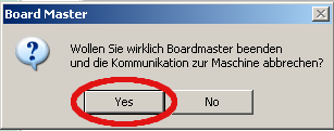
- Close BoardMaster. You will get several dialogs:
- Stop the communication with the machine (yes)
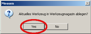
- Replace milling tool in the placeholder (yes). If you do not then when the next person uses the machine has to pay attention and select which tool it is.
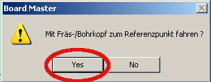
- Move the head to the reference position (yes). This will move the PCB tray back under the milling head - that's why you took out your PCB beforehand, right?
- Stop the communication with the machine (yes)
- After BoardMaster has exited, turn off the PCB mill using the side switch.
- Clean up any files you left around. Move them to your home folder on oliver if you'd like to keep them. The milling Mac and its Windows virtual drive may be erased at any time! Your data on this machine is NOT backed up. You've been warned.
- Quit Parallels (Cmd-Q). From the dialog, select Turn Off to safely shutdown the virtual Windows session.
- Log out from the Mac.
- Select universal cutter (8 mill) (or the tool you want to calibrate)
- Move the milling head to an empty position on the material with the move button {IMG(src="http://hci.rwth-aachen.de//files/migrated/images/fablab_mill_tutorial_BoardMaster_head_move_button.png")}{IMG}.
- Press the button to start turning the milling head
 then lower the head on the material
  .
. - Manually move the head a couple of mm to the front (4-6 mm in series of 2 or 3 mm) to get a sample of the current settings.

- Press the button to lift the head and the one to stop it from turning .
- Move the camera to the head by selecting in the menu: Verfahre nach \ Kamera -> Kopf
- Manually move the head 1-2 mm back so that the engraved line is in view.
- Click on one side of the line where the line is constant (in between points) and then on the other, making sure that the line is straight. There will be the length of the line in red on the camera picture.
- Move the camera to the head by selecting in the menu: Verfahre nach \ Kopf -> Kamera
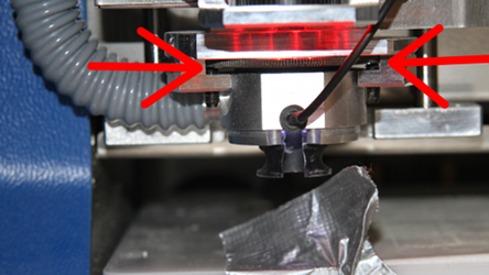
- If the measure did not match the tool then you meed to open the hatch and manually adjust the head height by turning the gear-like wheel that is somewhere on the top of the milling head but under the level of the camera. Turning the gear to the right pulls the head up (for when the line is longer) and to the left lowers it (when the line is shorter). If the measure is close enough the you are done.
+# Single-sided Boards using TOP layer (e.g. SMD projects)
If you have a single-sided board with SMD parts on the TOP layer :
+# Single-sided Boards using BOTTOM layer (e.g. THP projects)
If you have a single-sided board with through-hole parts on the BOTTOM layer :
+# Double-sided Boards
milling double sided boards (including fiducials)If you have a double-sided board:
Milling
-
Now we step the mill through its phases. For each Phase once it's finished, you get a confirmation box showing the duration of the mill. Click OK.
Don't leave the mill while it's running. If something happens, open the transparent door, and the mill will stop immediately.
+# Turning things off
+#Advanced uses
+#PCB with cutouts
+#Phase settings explained
+#Manual Isolation in CircuitCAM (for better soldering)
+#Calibrating
+# FAQ
+# Error listing
!+# Terminology