Fabscan tutorial
How to make your own FabScan 100?
creating and assembling the body parts
what you need:
32 screws| length : 16mm, diameter:3 mm38 nuts for 3 mm diameter
6 screws|length:10mm, diameter 3 mm
6x: 60cm x 30cm MDF sheet 5mm thick
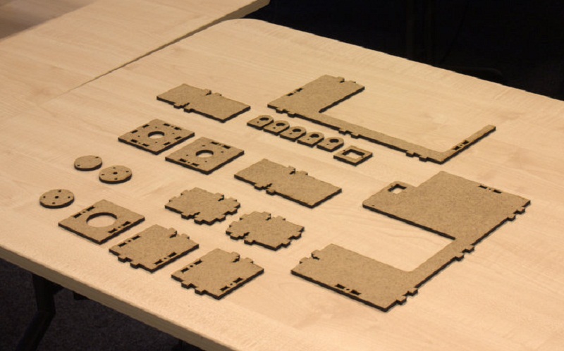
Cutting the MDF sheets
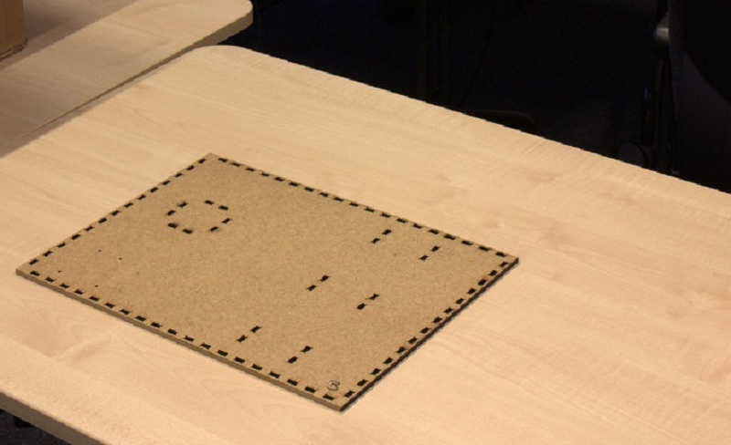
use the files below to lasercut the MDF sheets, the images below each link demonstrate the achieved piece after cutting Piece A:Box Back and Middle BoxBackMiddle.svg Config:Power=100, speed=30, focus=0.0, frequency=500
Estimated time:7'50"
Note: the diameter of the turntable is slightly smaller then the circle to have some space to move!
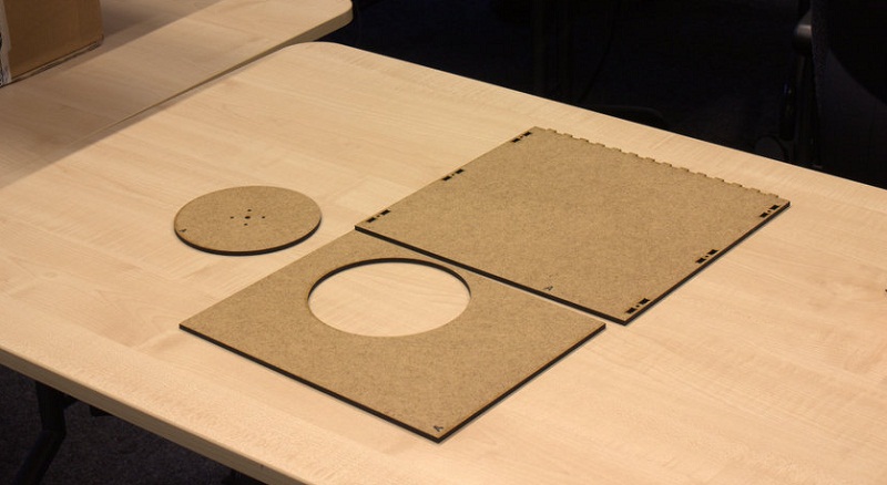
Piece B:Box BottomBoxBottom.svg Config:Power=100, speed=30, focus=0.0, frequency=500
Estimated time:8'10"
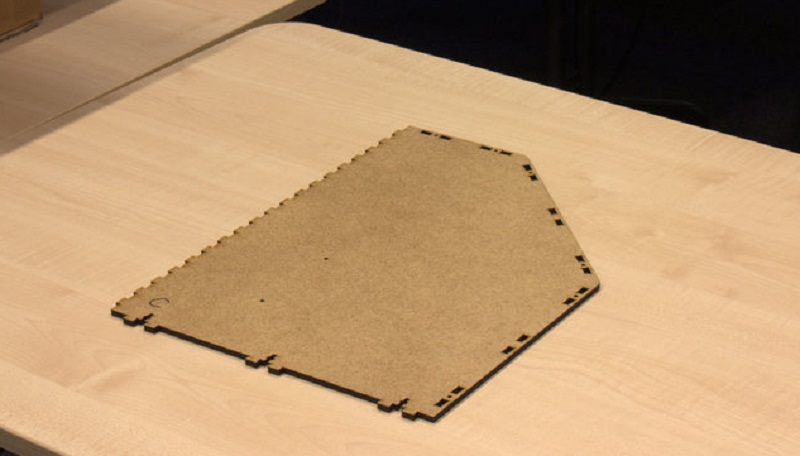
Piece C:Box Right Side
Config:Power=100, speed=30, focus=0.0, frequency=500
Estimated time:4'58"
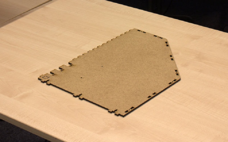
Piece D:Box Left Side BoxLeftSide.svg Config:Power=100, speed=30, focus=0.0, frequency=500
Estimated time:5'26"
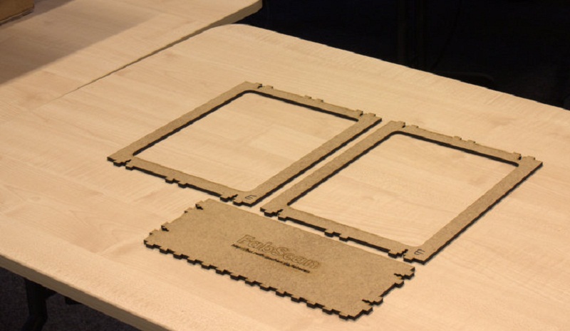
Piece E:Box Top Slope FrontBoxTopSlopeFront.svg Config:Power=100, speed=30, focus=0.0, frequency=500
Estimated time13'25"
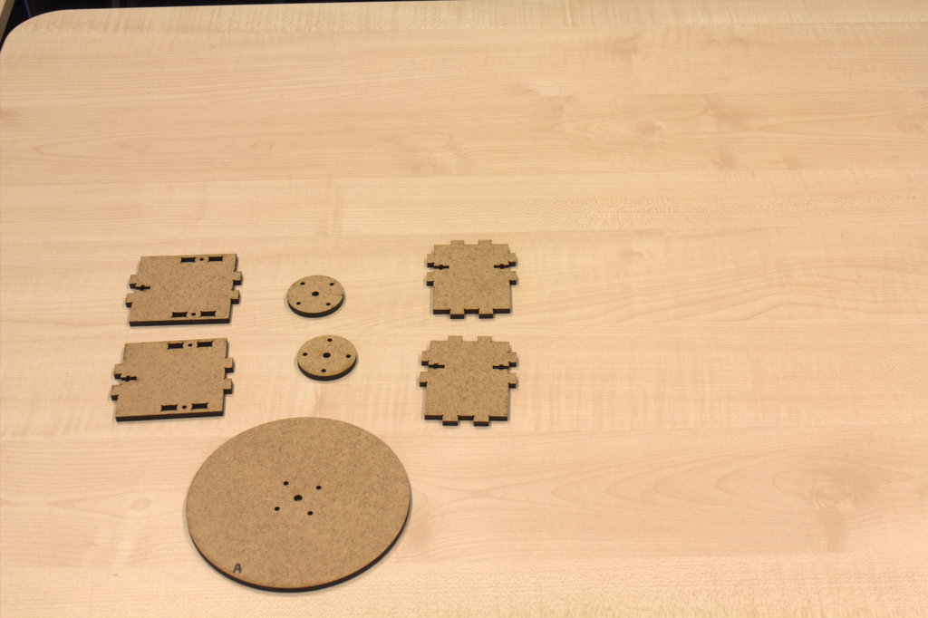
Piece F:Holders Laser Turntable CameraCamLaserTurnTableHolder_othername.svg Config:Power=100, speed=30, focus=0.0, frequency=500
Estimated time18'24"
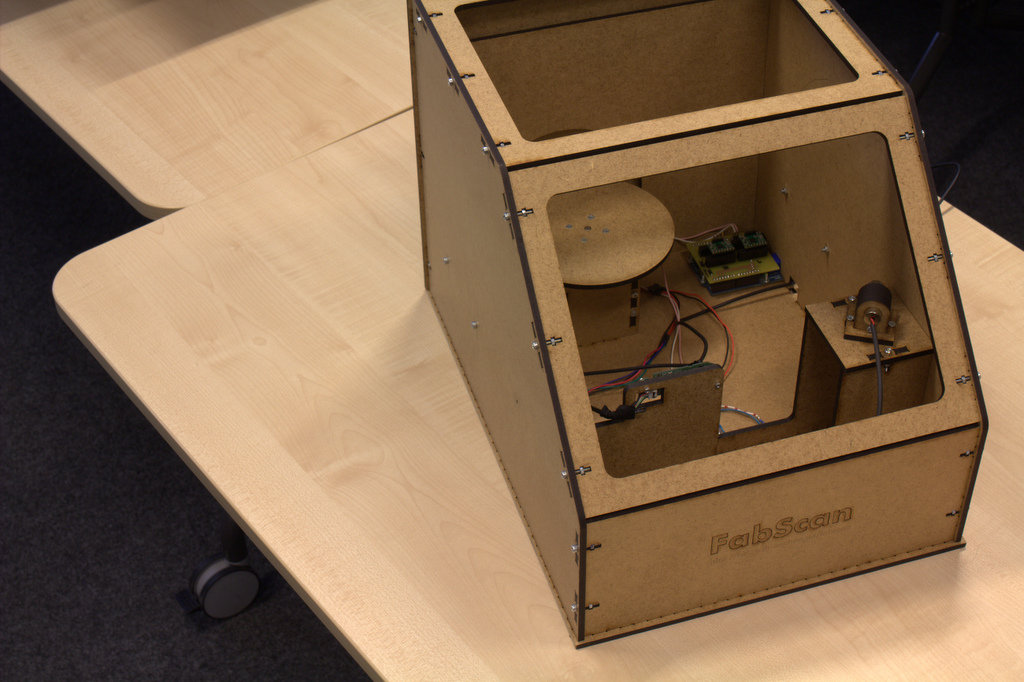
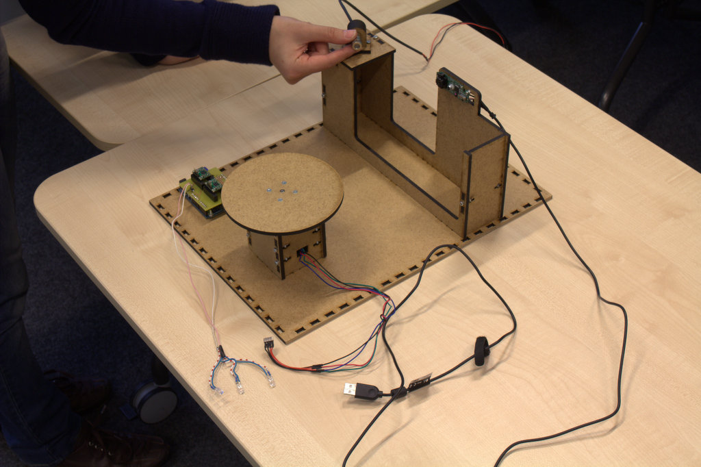
Assembling the parts together
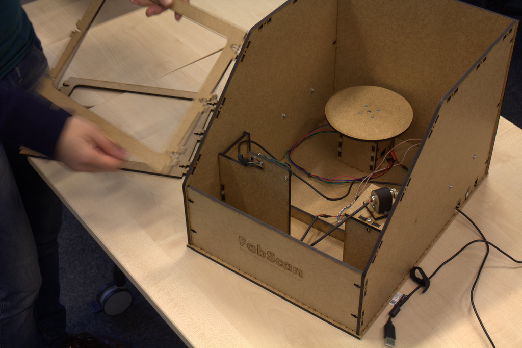
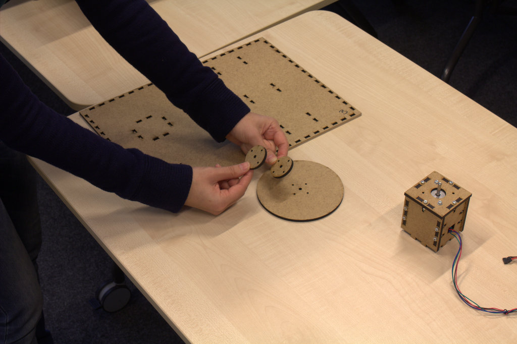
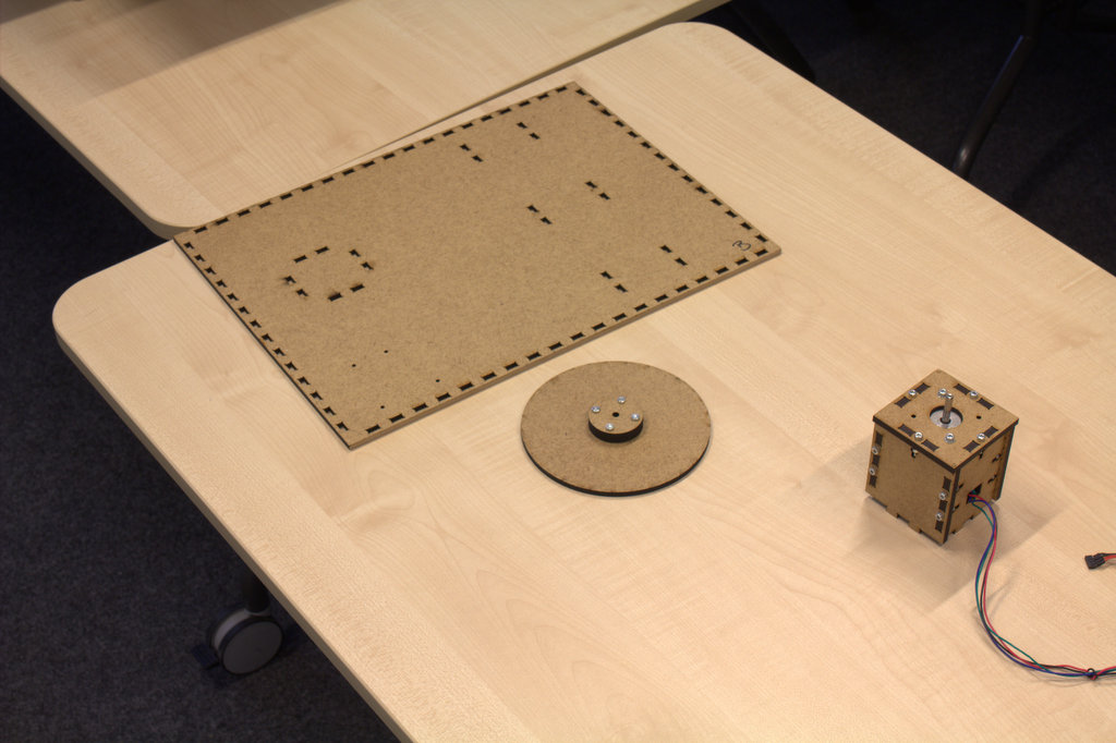
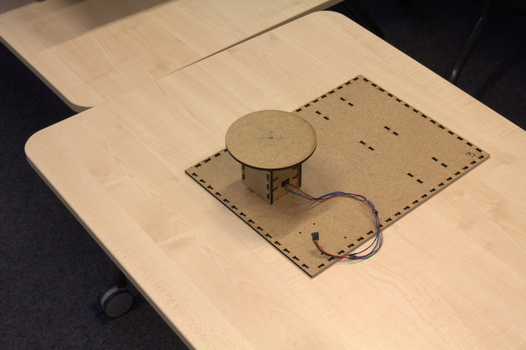
Assembling the turning table
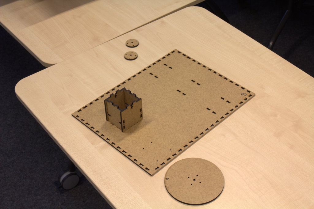
note: better first fix the four walls of table base together then attach it to the ground piece (piece B).
.jpg)
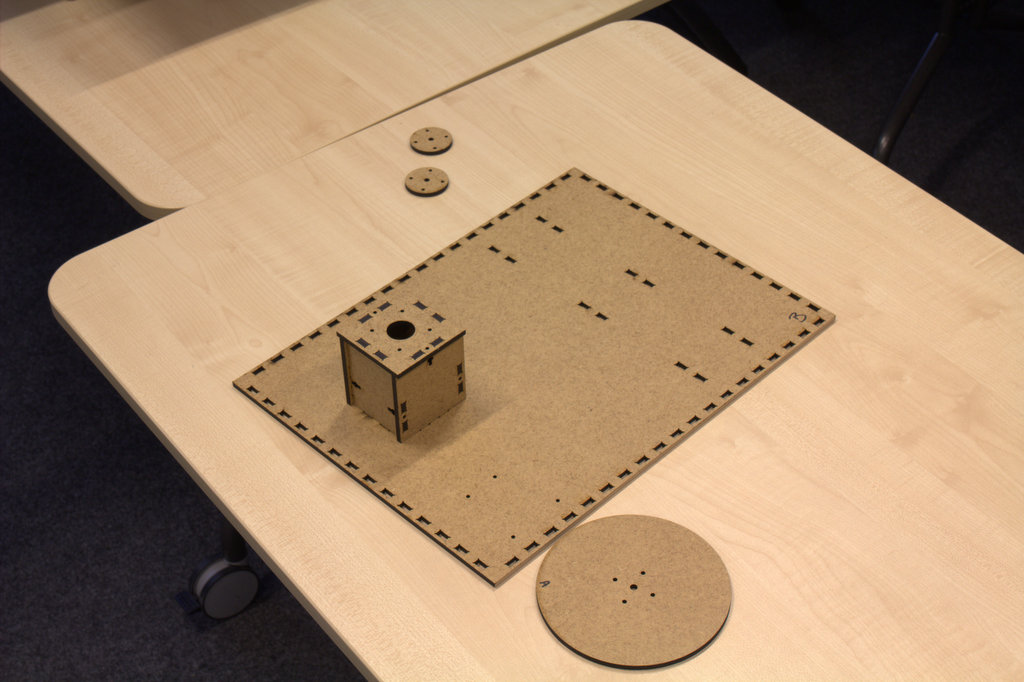
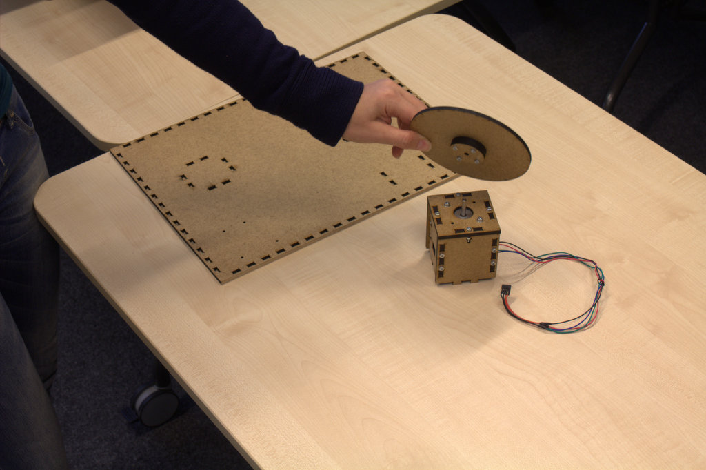
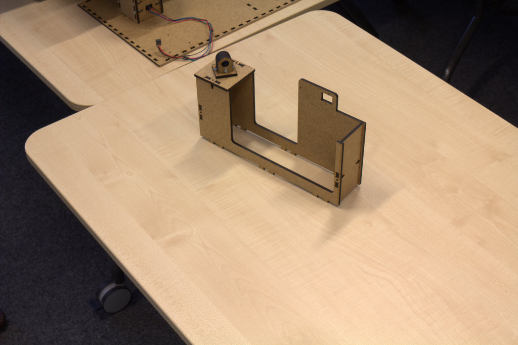
Assembling the camera and laser holder
note attach all the parts together first and then attach the hole unit to the ground piece (piece B)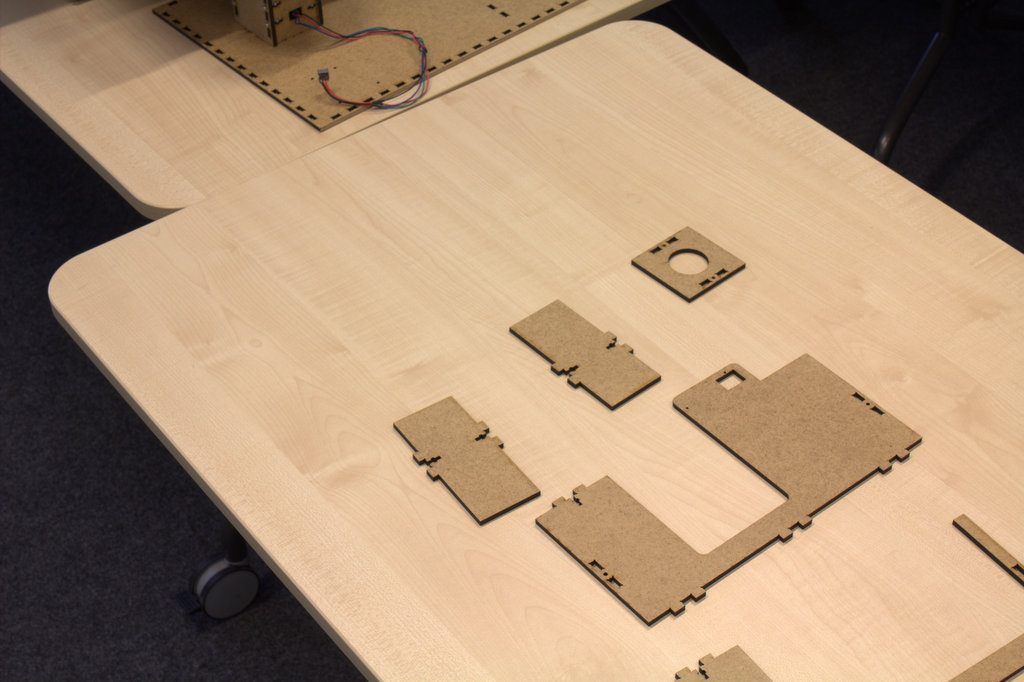
.jpg)
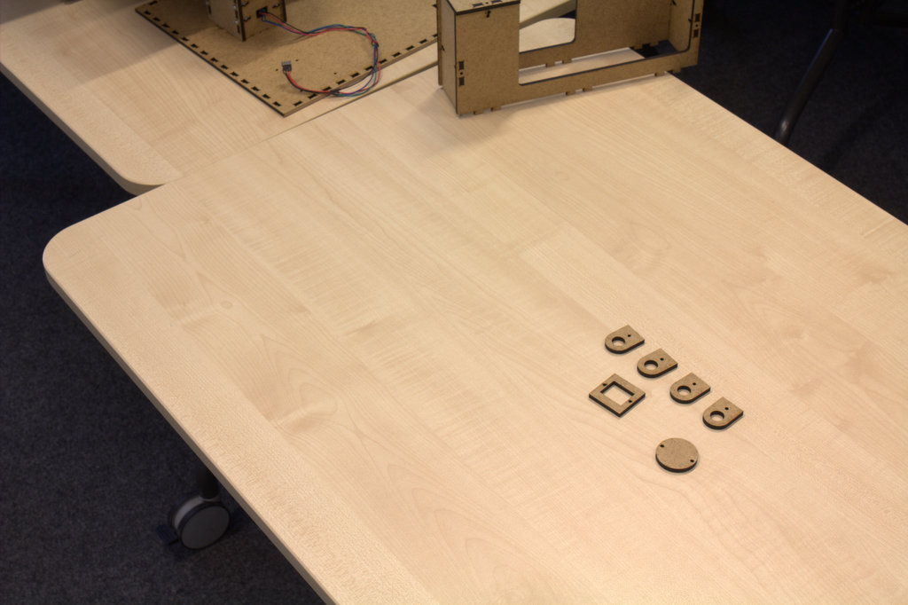
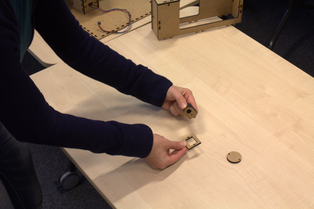
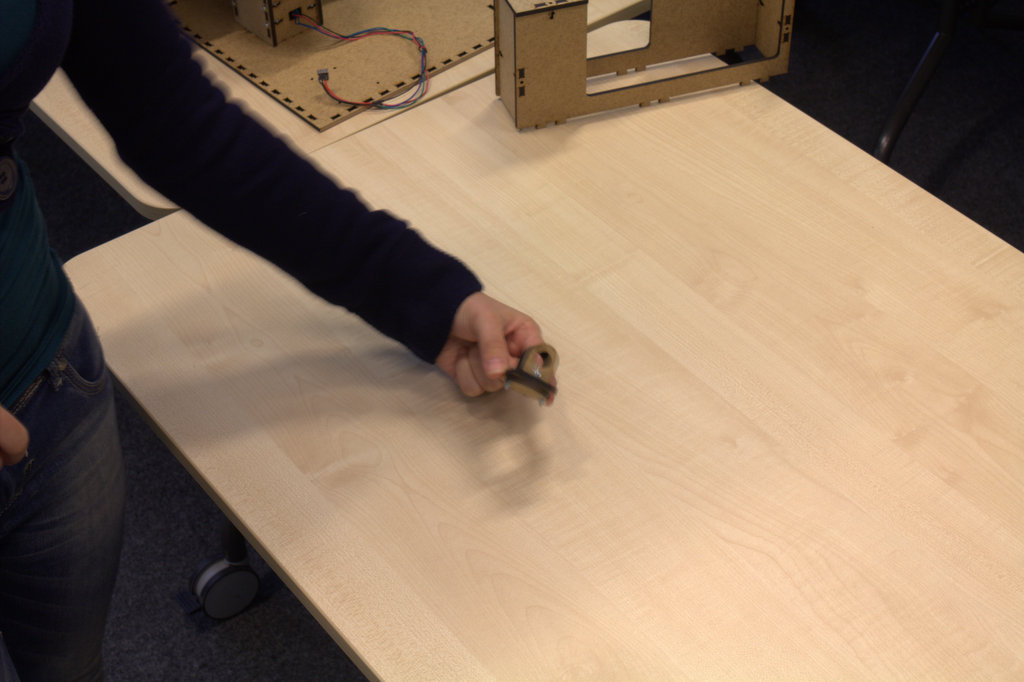
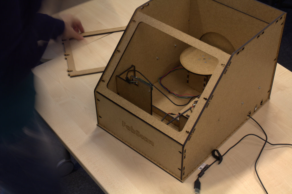
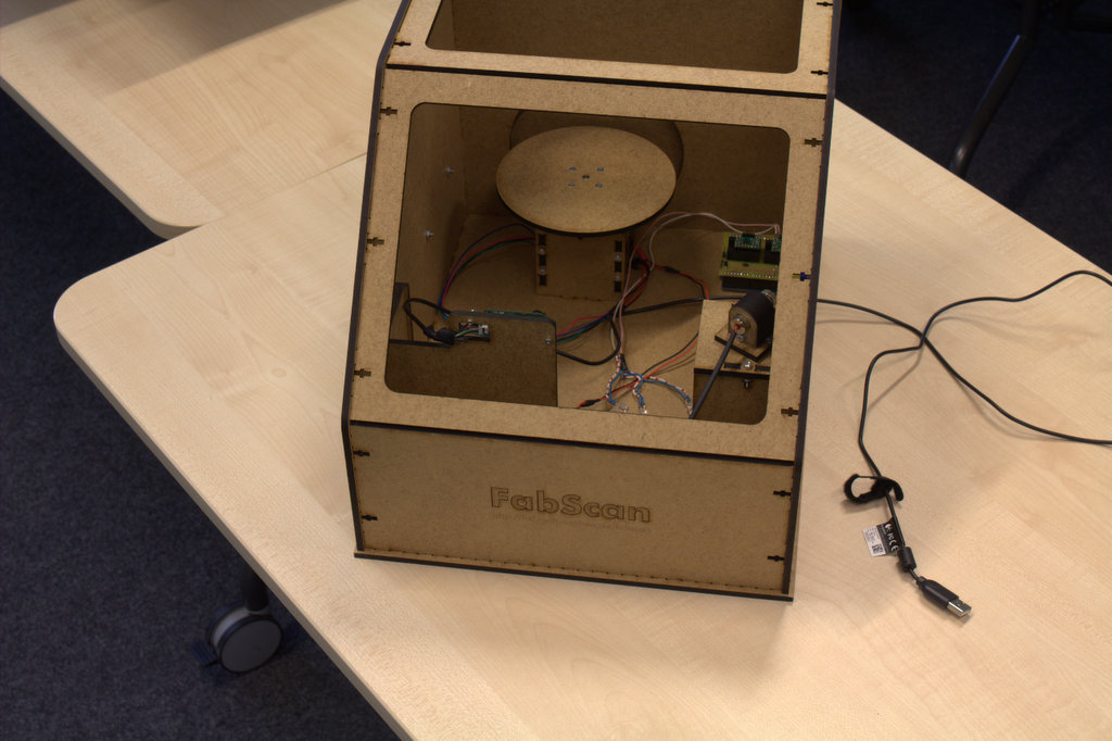
Implementing the camera, the laser and the motor on the holders
note: do not forget to fix everything together using screws and nuts!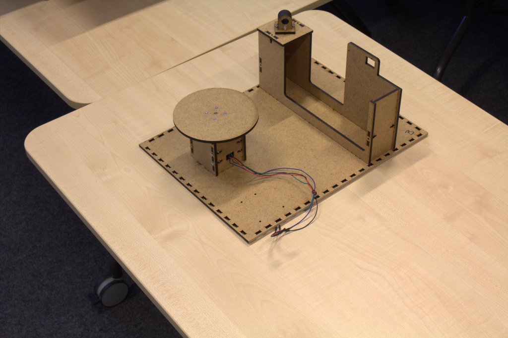
.jpg)
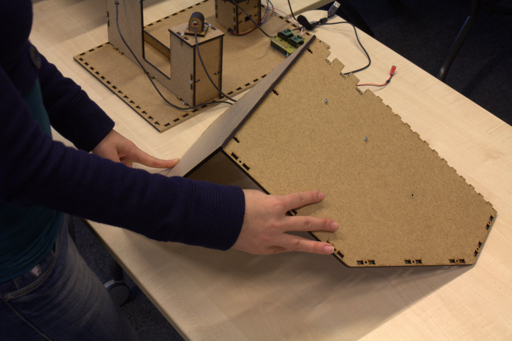
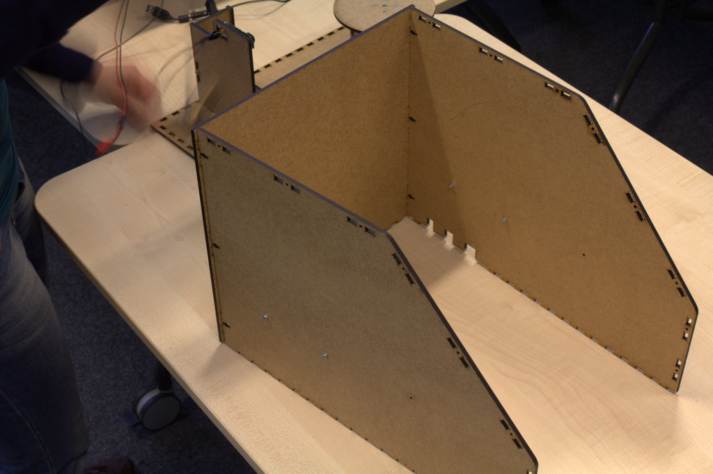
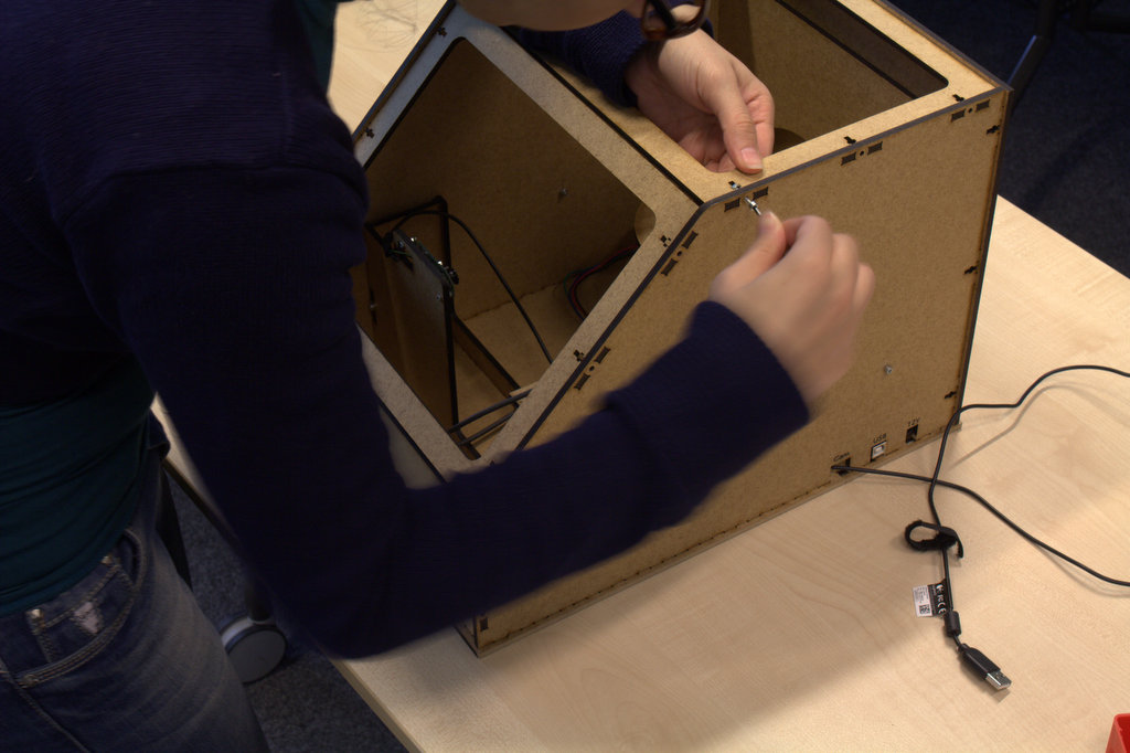
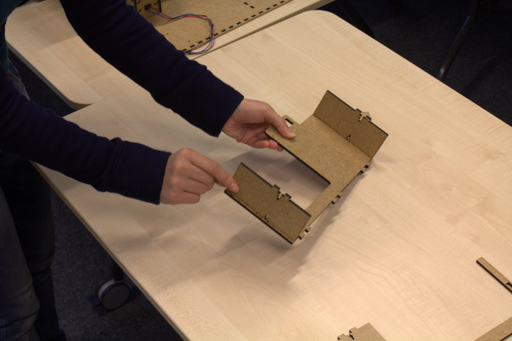
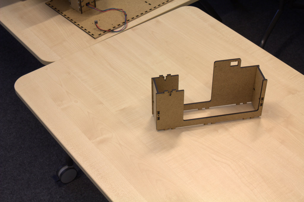
Assembling the walls of the box together
The best way to do it: 1.Take piece D2.Attach all pieces of E to D(the biggest piece stands on the top)
2.1.Tighten the pieces together using screws
3.Attach piece C to the pieces E.
3.1. Tighten the pieces together using screws
4.Attach the back part (Part A ) to parts E,D and C.
5.Attach the whole unit to the ground piece B.
6.Fix everything together using screws and nuts wherever required