Simple guide for milling with Fusion 360
In this guide we describe how to use the milling machine for a very basic and easy task. Let's assume that you have a board of a size of 60x40 cm with a thickness of 6 mm and you want to mill out smaller bread with the size of 30x20, which you have modeled in Fusion 360.
+# Initial setup
Procedure about opening the doors and placing the plate on the work area and fixing it using the metal plates
+# adlasd
+# Fusion 360
In Fusion 360 we will model our frame, which we want to mill in the end and tell the milling machine what needs to be done.
+# Axes
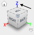
Before we start modeling, there is one thing which will make later work way easier (it also helps a lot when moving and rotating the camera). Since our machine is using the Z-axis for depth, we also want that here. So in case the upper right corner does not look like in the picture below, we need to change this.
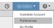
You can set this up in preferences (top right corner, click on your account name first)
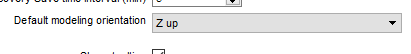
in the field Default modeling orientation and select Z up.
Now we can start modeling our frame.
+# Modelling
We could model the whole board but since we only care about the frame, we will only model this particular frame.
Since the frame is a block with a rectangular hole inside, we choose the Create - Box option to get started.

After this selection, we need to choose the plane. We select the X/Y plane by selection the "bottom" plane.

The next step is selecting the point of origin, from which we want to start creating our box. You can do this anywhere you want but we recommend starting from the origin of the coordination system.

Now you will see that you can drag the mouse somewhere and it will determine the width and length of our box. You can either drag the mouse or you can also just type the measurements into the text fields (first move the mouse somewhere, and then just type the numbers, you don't need to select the text fields). Our box frame won't have the same width and length, and our milling machine also has a longer axis and a smaller axis, with Y being the longer one.
You can see in the upper right corner that the Y axis is green and the X axis is red. Use this for orientation and to type in the measurements correctly since those colors also correspond to the actual coordination system you are now using for the box. Confirming will show an actual model of the box, now asking for the height. You can also check the measurements here in case you did something wrong.


Our board has a thickness of 6 mm, so we type "6 mm" and hit OK or Enter to confirm. This gives us our 3D box.

These were all the necessary steps in the modelling process and we can now continue with the steps to generate the milling process.
+# CAM
First switch from Model mode to CAM mode by clicking on MODEL and then selecting CAM in the upper left corner. CAM stands for "Computer-aided manufacturing", so in this mode we set up everything in order to generate code which the milling machine will use to process.

+# Tool Library
First we need to make sure that all the tools are available. By tools we basically mean the milling heads, the part which will drill into the material and remove parts of it. At the FabLab we have our own set of tools to use for milling. In Fusion 360 you have a library with tools and all their parameters. This guide is aimed at users who use the MacBook in the FabLab which is connected to the Stepcraft machine, which means that our tools will be loaded in Fusion 360. In case you work from home, please refer to xxx where we show you how to load up our tools in your own Fusion 360.
+# Toolpaths
Now that we made sure that the tools are available, we can generate the so called toolpaths, which determine how the milling head will move around.
+# Setup
Before we can start choosing the milling operation, we first need to adjust some options. We first create a general milling setup by clicking on the respective icon in the tool bar.

This will open up the setup dialog and a new point of origin should appear in the middle on top of the box.

To make later estimations - concerning the measurements with the actual milling machine - easier, we can place this point of origin on the lowermost vertex by clicking on the top point (out of the three possible points).


This way, the X axis will go along the shorter side, Y will go along the longer side and Z will go up, just like the orientation of our milling machine.
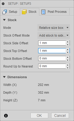
Next, in the setup dialog, we switch to the second tab Stock, where Fusion sets an offset of 1 mm for both Stock Side Offset and Stock Top Offset by default. We set those to 0 mm.

That's it for the setup, so we can confirm it via OK.
+# Operation
For our project we just want to cut out a part, which means that we just want to cut around the edges. For this purpose we select the so called 2D Contour from the 2D menu.

This opens up the respective dialog, in which we need to set some things up.
- First Tab: Tool
First off, we need to select the tool we want to use for this task by clicking Select... next to Tool, which opens up our tool library we have seen before. Since our material has a thickness of 6 mm, we can use the default tool xyz in our Tool Library and hit OK. The name of the tool should now appear below the Select... button and a transparent tool should appear above the point of origin like in the picture below.

By default, Fusion 360 selects a Coolant (in most cases Flood), but we don't use one so we can choose Disabled here.
- Second Tab: Geometry

You might have noticed that after you selected the contour operation, edges of your model are highlighted when you hover over them. This is because the first option Contour selection of this tab is automatically selected as you can see now, even when you are not on the second tab. Which means that we now have to select the contour of the element, which outline we want to cut.
Since we want to cut out our whole box and not just engrave an outline, we select the lower edges of our box by clicking on it.


The chosen contour should be now highlighted in blue and in the dialog it should say Chain next to Contour selection. In case you did something wrong, you can click the x to the right side of Chain and repeat the process.

This is the only step for this tab so we can move on to the next one.
- Third tab: Heights
When selecting the third tab, you should now see some colored layers appearing. However, we don't need to bother with most of them. We only need to make sure that the Bottom Height is set correctly as this determines to what depth the milling machine will go. By default Selected contour(s) should be selected next to From. We choose Selection from the menu instead and then click on the lower edge, just like when we chose the contour.


It should then read Edge next to Bottom Reference.
These were all steps necessary for our only operation, so we can now confirm the dialog via OK.
After closing the dialog, Fusion computes the the toolpath. Due to this, it can happen that the transparent tool is now on the other side of the box with two arrows and a blue line surround the box.
The red arrow indicates the starting position while the green arrow indicates the ending position. Blue paths show milling paths, yellow lines show paths for moving the milling head, the red line indicates drilling movement into the material, and the green lines indicate "ramps", where the milling head leaves the material.

This was it for all the necessary steps to set up the milling operation. Before we generate the code, we can simulate the process to check, if everything is set up correctly and also get a rough estimate of the time the process will need.
+# Simulation
For this, we click on the simulation button in the tool bar. This opens up the simulation dialog, shows up "media" buttons (1) in the lower area of the screen to control the simulation, and also a green timeline in the lowermost part of the screen (2).

Just click the play button to start the simulation and you should see the tool coming down and moving around. You can adjust the speed using the circular button (3).
Now take a look at the timeline at the bottom. If everything works as intended, you should see one completely green bar. If there are any collisions, red lines should appear there and other colors if anything else would occur during the process. However, if you followed our guide thoroughly, it should all be fine.
Additionally, you can mouse over the bar and you can see an estimate of the Machining time.

If the simulation shows what we want to do and everything looks correct, we can continue with the final step in Fusion 360 and generate code for the machine and export it.
+# Post-processing

Click on the icon with G1, G2 in the toolbar to open up the Post process dialog.
Now we again assume that you are doing this on the notebook connected to the milling machine. In case you work from home, please refer to xxx where we show you how to load up the necessary files for this step.
Make sure that your setup looks similar to the picture below.

- 1. Make sure that STEPCRAFT UCCNC / stepcraft uccnc is selected here but it should be by default
- 2. You can give your file a name here
- 3. And if you want a comment
After this, click on Post to open a dialog where you can choose where to save the file.
This was it for Fusion 360, but since we cannot access the milling machine there, we need to open up the generated file in UCCNC, which will handle the communication with the machine and read our generated file.
+# UCCNC
Screen of UCCNC in the taskbar