Stepcraft 840 CNC Router
Back to Tools : Mills and CNC RoutersThe current and updated documentation for the Stepcraft using Fusion 360 and UCCNC can be found here.
The Stepcraft is suited for milling of 2D and 3D models with materials such as wood or aluminium. Because of lots of different factors which can be considered and some of them need to be considered, we will discuss those in particular.
File formats
In terms of 2D milling WinPC-NC accepts the following file formats: .plt, .opt, .dxf, .eps, .ai Which means typical .slt_ or .svg files need to be converted into one of these formats first.Inkscape is suited very well to draw 2D engravings, which can then be exported as .plt files.
Fusion 360 Future work
Material
In general there are 2 materials required to mill, which are put onto the working surface.Procedure
The native software for the milling machine is WinPC-NC, which is installed on the MacBook via Parallels.At first both materials are placed onto the working surface, whereas the sacrificial plate is to be put down first and on top of it the actual working piece material. The metal "downholders" then need to be fixated into the slots on the sides of the milling machine so that they keep both materials down. Additionally screws should be tightened into some of the holes of the downholders in order to fixate the material even more (this can be done by hand or via an electric screwdriver). Yes, fixating and moving the downholders can be very hard.

After this the milling machine can be turned on. For this it should be connected to a power socket and also to the USB port of the MacBook. On the left side of the machine you can find LEDs which indicate the status. It should look like this in order to function properly:
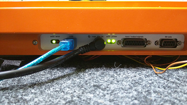
If it does not, please refer to the manual as it helps with troubleshooting.
Edit: Inside of the enclosure, the LEDs are not easily visible at the back of the enclosure. As of right now, there is no practical solution to this issue aside from opening the doors and trying to look around to see the LEDs.
If you now open up WinPC-NC, a second small window should open up, which shows if the machine was connected properly:

If the name of the milling machine is shown in orange letters like in the picture below, everything is correct.
Now you can load up your sketch you want to mill via
 , which will show up a preview in a coordinate system. With this you can check the measurements and dimensions of your sketch. If you want to mill the sketch in different measurements, the different axes can be adjusted as we will explain in the next steps.

However, the orientation is not the same as the one you see in the preview. In the picture below you can see what the result of this sketch looks like. This means that the final result will actually be turned 90° counter-clockwise.

The third toolbar shows all the single outlines indicated by color and numbers. For example in the figure below you can see that 1 and 6 are outlines. By clicking you can hide/unhide them which sets up if those will be considered or not for the milling process. This way one could for example mill only the sketch itself but not the outer outline.
Clicking Parameters > Tools will open up the settings, in which some parameters need to be set. For example, when the measurements for the actual working piece material differ from the sketch file, this can be set up in the tab Coordinates. There you can set up the scaling factor for every axis. After changing those, you will see the results in the coordinate system and can check if it will have the planned size regarding the working piece material which will be milled.

When the size is as planned, the parameters for the materials have to be set. In Parameters > Tools > Measure the plunge depth (in mm) can be set for every outline.

If the working piece material is 3mm thick, a depth of 1mm should be enough for the actual engraving. The outer contour should be 4mm so that it will drill through the first material.
Before the actual milling process can be initiated, make sure that the right drill head is put and fixed inside the drilling machine. Afterwards adjust and fix(!) the drilling machine with the Allen screw ("Imbus" Schraube in German) seen in the picture below. Also the hose of the vacuum cleaner should be fixed to it.

Now that the physical components are set, the working area of the milling machine needs to be set up. If it is not yet, turn it on by connecting it to a power socket and also via USB to the MacBook.
Before you actually control the arm of the milling machine, go to Parameters > Speed and make sure that the values are set to those like in the picture below. Those values are set up for the drilling machine we use and shall not be changed! Usually they are already set up like that and do not need to be changed but in case they are different, make sure they correspond to the ones below.

Open up the manual mode
 . Here you can manually move around the "arm" with the arrow buttons and automatically move to certain points via Move to....

The first thing to do is to move the arm to the zero point on the X and Y axis. It is advised that this point still leaves space of 50-70 mm to the edges. This will be the same point corresponding to the "cross-hair" you can see on the sketch preview in one of the corners. In the picture with the sample sketch it's the lower left corner. You can do this by either actually marking this corner with a pen or just picturing an X.
Move the arm with the arrow buttons until the drill is right above the X. You can also move it down and up using the arrow buttons on the right side to make sure that it is where you want it to be. However, before the next step the drill has to be at half of the max height in the Z axis (see picture below)!

When you are sure it is the right position in terms of X and Y axes and the Z axis is at half of the max height, click on Save to... > Zero point XYZ .

After clicking, the arm will automatically rise 10 mm in the Z axis. The coordinates for the work piece should now be like this:

Having set up these 2D axes, the sketch can be tested. For this, remove the drilling machine for safety reasons (you can leave the hose). Afterwards you can just click on Move > Start. A little window will appear which shows the progress in percent and offers the option to Stop. This is a safe and good method to see if the size of the sketch fits the working piece area.
In case the arm did not overpass the edges or borders, the drilling machine can be put back inside the lock and fixed again. Since the X and Y axes were set correctly, the Z axis has to be set up now. Open
again and click on Move to... > Zero Point XY. After the arm moved to this position, take a piece of paper and put it on the working piece material beneath the drill. Now move the arm downwards using the manual control until the drill head gets in contact with the paper. Stop as soon as it touches it and save this position via Save to... > Zero point XYZ.
This was the final step to set up all the necessary parameters. In order to start the milling properly, make sure all things are fixed properly and then turn on both the drilling machine and the vacuum cleaner. The milling process can then be initiated again with Move > Start. During the process you might notice that the vacuum cleaner we use might not suck up all the dust produced by the drill and in case there is too much dust, it is recommended to suck it up manually by hand, holding it close to the drilling.
Open Questions:
Fixating the material so it won't slide around?
Status: Currently investigating
Adjusting the milling paths so that elements do not become loose
Status: Currently investigating
It seems that Inkscape allows to use different colors so that in WinPC-NC only one part can be milled first and then other ones. Another method is to use Estlcam, which allows to set up the milling paths for a given sketch file.
Milling heads
Status: Awaiting discussion
The following list contains milling heads we could order and use for our stepcraft. However, as far as I understand, these are only for wood. But I can look into it in more detail when this is discussed.
| Diameter | Max. milling depth | Shaft | |
|---|---|---|---|
| T-TR01X8MMTC | 3.2 mm | 12.7 mm | 8 mm |
| TI-M310-70-8 | 3 mm | 10 mm | 8 mm |
| KLE-T162-030-R | 3 mm | 12 mm | 8 mm |
| TI-M2-58-8 | 2.5 mm | 8 mm | 8 mm |
| T-2-08XMMTC | 1 mm | 3 mm | 8 mm |
| T-3-06X8MMTC | 2 mm | 5 mm | 8 mm |
| E-10352 | 3 mm | 8 mm | 8 mm |
| TI-M410-70-8 | 4 mm | 10 mm | 8 mm |
| E-10350 | 2 mm | 6 mm | 8 mm |
| T-C001AX8MMTC | 3 mm | 9.5 mm | 8 mm |
| T-DH-01X8MMTC | 1.6 mm | 5 mm | 8 mm |
| T-DH-02X8MMTC | 2 mm | 5 mm | 8 mm |
| T-3-1X8MMTC | 5 mm | 16 mm | 8 mm |
| E-10354 | 4 mm | 12 mm | 8 mm |
| E-10358 | 5 mm | 20 mm | 8 mm |
| T-3-3X8MMTC | 7 mm | 19 mm | 8 mm |
| E-10950 | 6 mm | 20 mm | 8 mm |
| E-10042 | 3 mm | 12.7 mm | 8 mm |
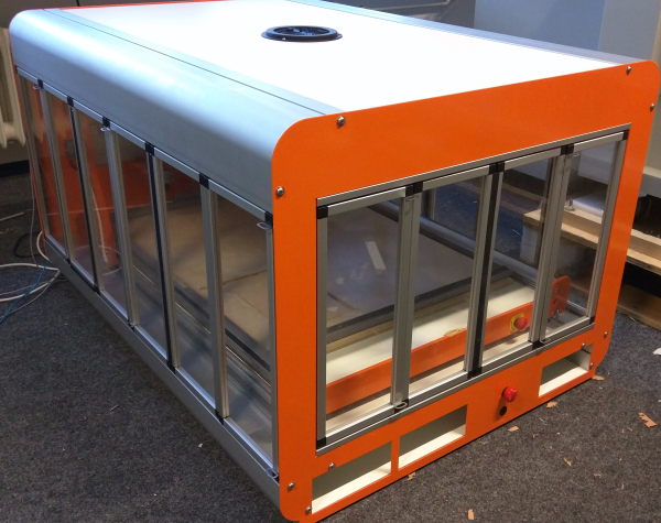
Enclosure issues
Status: Solved
After the Stepcraft machine was embedded into the enclosure, the milling itself works but there are some issues we are currently trying to fix:
- The Doors are not as flexible as they should be, especially the doors on the left hand side of the machine
- The enclosure offers sensors to check, if everything is closed before milling and also if doors are being opened while milling is in process. As of right now, the sensors state that the enclosure is not closed, although the doors are closed.
Workplace for the milling machine
Status: In work
Right now, the milling machine and the enclosure containing it, are placed on the floor in room 2010. Milling is possible but this might not be the best location for it.