Hardware
Ingredients
- One Teleo introductory module, provided by the chair
- 5 pressure/force-sensors (type FSR-149AS), bought by the chair at conrad
- several resitors, provided by the chair
- cables, provided by the chair
- undertaker gloves, provided by Gero Herkenrath
- one RFID reader and several RFID chips
- and of course patience, tape, a solding place and good advice by the people of the chair (thanks to Tico and Eric)
Construction
The construction of the glove consisted of several stages:
- attaching of the sensors and cables to the glove
- testing of different resistors and ways to attach it to the music glove
- the solding of the resistors to the cables and
- hiding the cables on the glove under a second glove that got put over the base-glove
The pressure/force sensors had a radius of 4 mm and an about 2 cm long strap for the solding contacts. Thus they had to be bent from the fingertip over the fingernail for this was the only possibility to put them on the glove without limiting the ability to make a fist for the person wearing it.
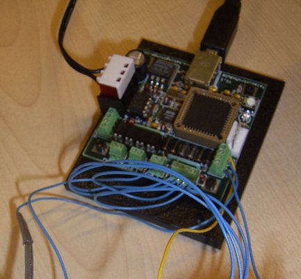
Teleo chipset connected
The cables to be put onto each contact were carefully measured, since they had to be long enough to also allow making a fist. That is why on the images they appear to be too long.
The yellow cables are those later to be connected to the Teleo module's power supply, the blue ones had to be solded to the threshold resistors. In this stage this was already clear so we decided to hide the spot were the five yellow cables merge into one on the back of the hand under the second glove.
After the sensors were put on the glove we started to measure their actual resistance when pressed or not. This allowed us to calculate the needed threshold resitors.
The thumb became a problem in the whole construction because it was not connected to an analog input port but to a digital one. The Teleo module demands 2 or more volt at the digital port to read a "1", less would always be "0". Unfortunately the internal resitor of that port was only 10 k Ohm, much less than the sensor when only slightly pressed.
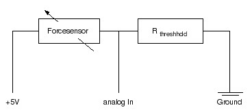
Connection diagram for a single pressure sensor
We found out that the thresholds had to be higher than the sensor resistance but at the same time lower than the internal resistance of the digital input port, i.e. it was impossible to connect it in the way we originally planned to.
Luckily, after some experiments we found out that it is also possible to just directly connect the sensor between the module's power supply and the digital input port. To tweak the sensibility to the point we wanted to we connected a fixed resistor in parallel to this setup.

RFID Reader placed into palm
The final outcome of the testing was to use about 1,22 M Ohm as threshold for the sensors on fore-, middle-, ring and little fingers' sensors and 30 K Ohm in parallel to the thumb's sensor. Any further adjusting of the sensitiveness of the sensors except for the thumb sensor was later done in the software.
The last step of building the glove was to actually sold the chosen resitors to the cables, put the second glove over everything and connect it to the Teleo module.
Not actually built into the glove was the RFID reader. For easier maintainance (e.g. loading the battery) it was simply slipped between the two gloves hiding the cables. Including the reader into our glove further was done in software only since nothing else had to be built.
- Authors: Malte Weiß, Gero Herkenrath, Tobias Schierge
- Last updated: Tuesday 07/19/2005
- Validate source: XHTML 1.0 strict | CSS 2.0