Haptic Vest 1.0
[Main Project Page] | [Haptic Toolkit Project Page] | [Haptic Vest 2]
History
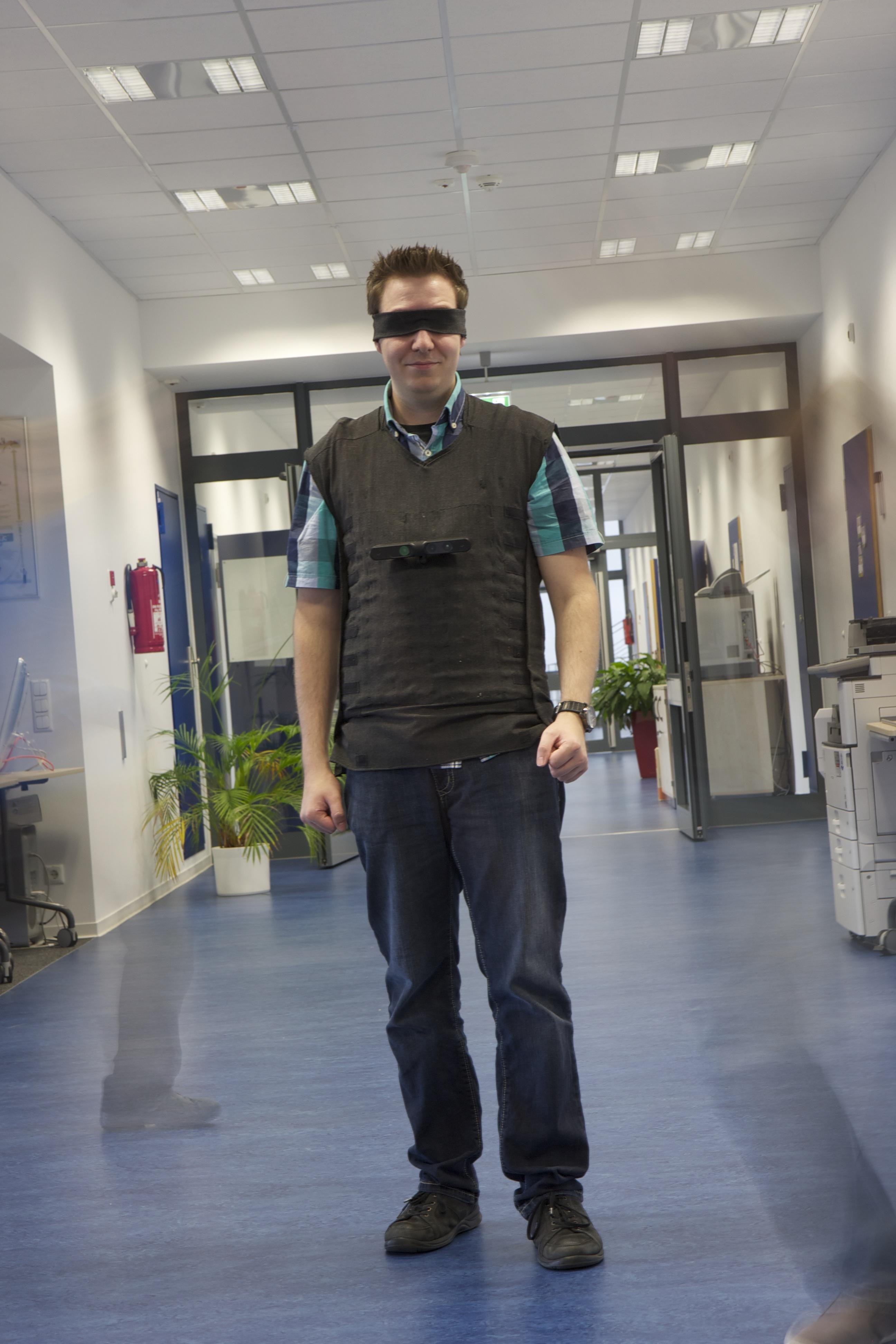
In 2015, David Antón Sánchez, under supervision of René Bohne, built OpenVNAVI: A Vibrotactile Navigation Aid for the Visually Impaired. The OpenVNavi vest was inspired by a similar prototype that Sean Benson built for Hackaday, but has a much higher resolution.
While the vest worked surprisingly well, we had issues with reliability when the vibration motor got stuck in its 3d-printed housing. Furthermore, soldering all the PCBs and wiring was complicated in this version of the vest.
Personal Photonics Proposal Gets Accepted!
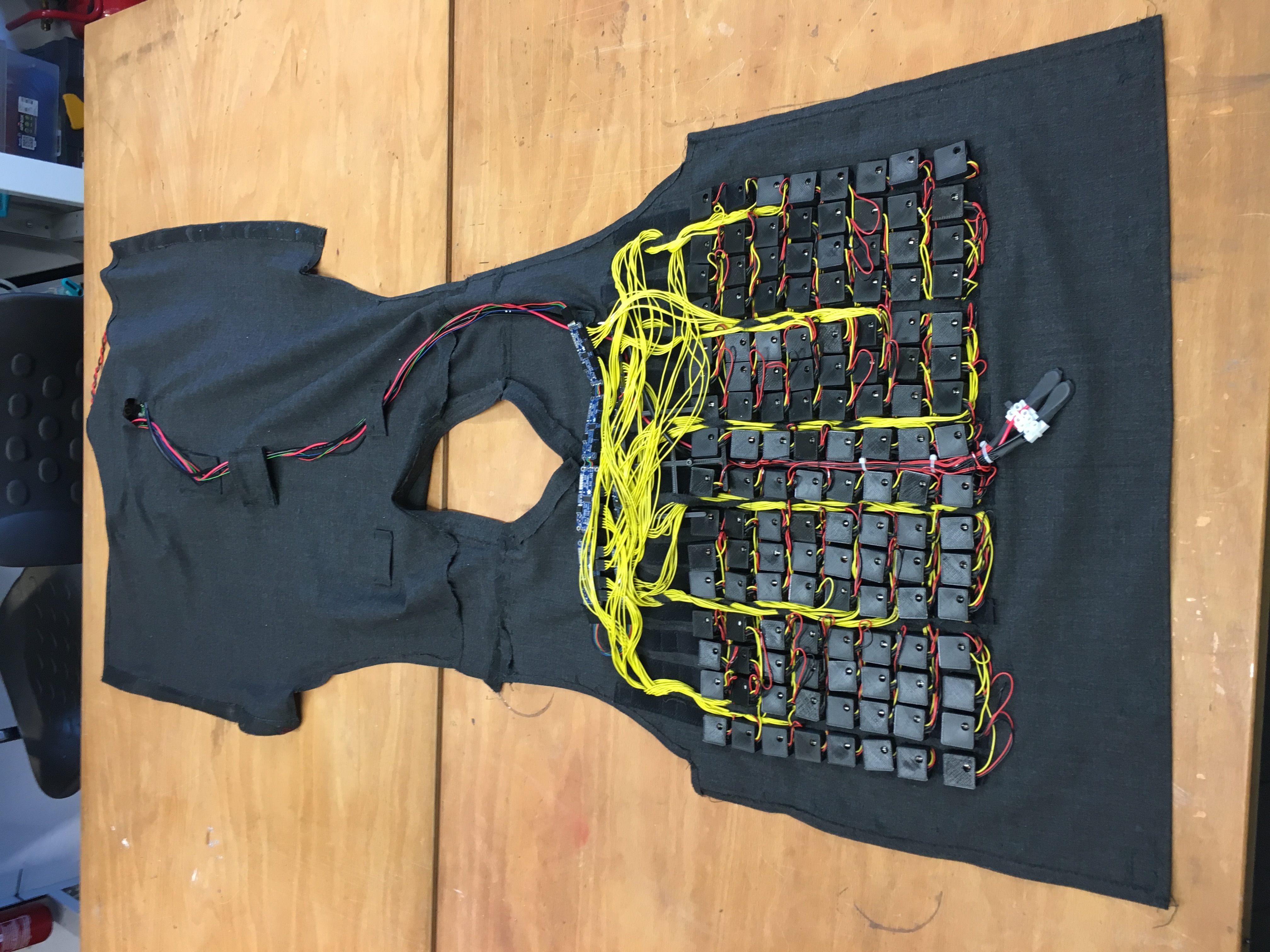
In June 2016, we acquired funding from the BMBF, as part of their Open Photonics call, to improve the vest and develop a haptic hardware toolkit to easily prototype different types of haptic feedback systems. We first reduced the amount of wiring in the OpenVNAVI vest by exchanging the central I2C expander hub on the backside with 8 Adafruit 16*Servo boards on the front. This made it easier to maintain the vest and reduced its weight, but resulted in a less balanced vest since the front part was now far heavier than the back part. We demoed this vest, Haptic Vest 2.0, at different conferences and makerfairs, and continuously refined the hardware.
We now describe the features of Haptic Vest 1.0.
Control Several Vibration Motors:
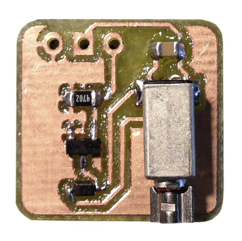
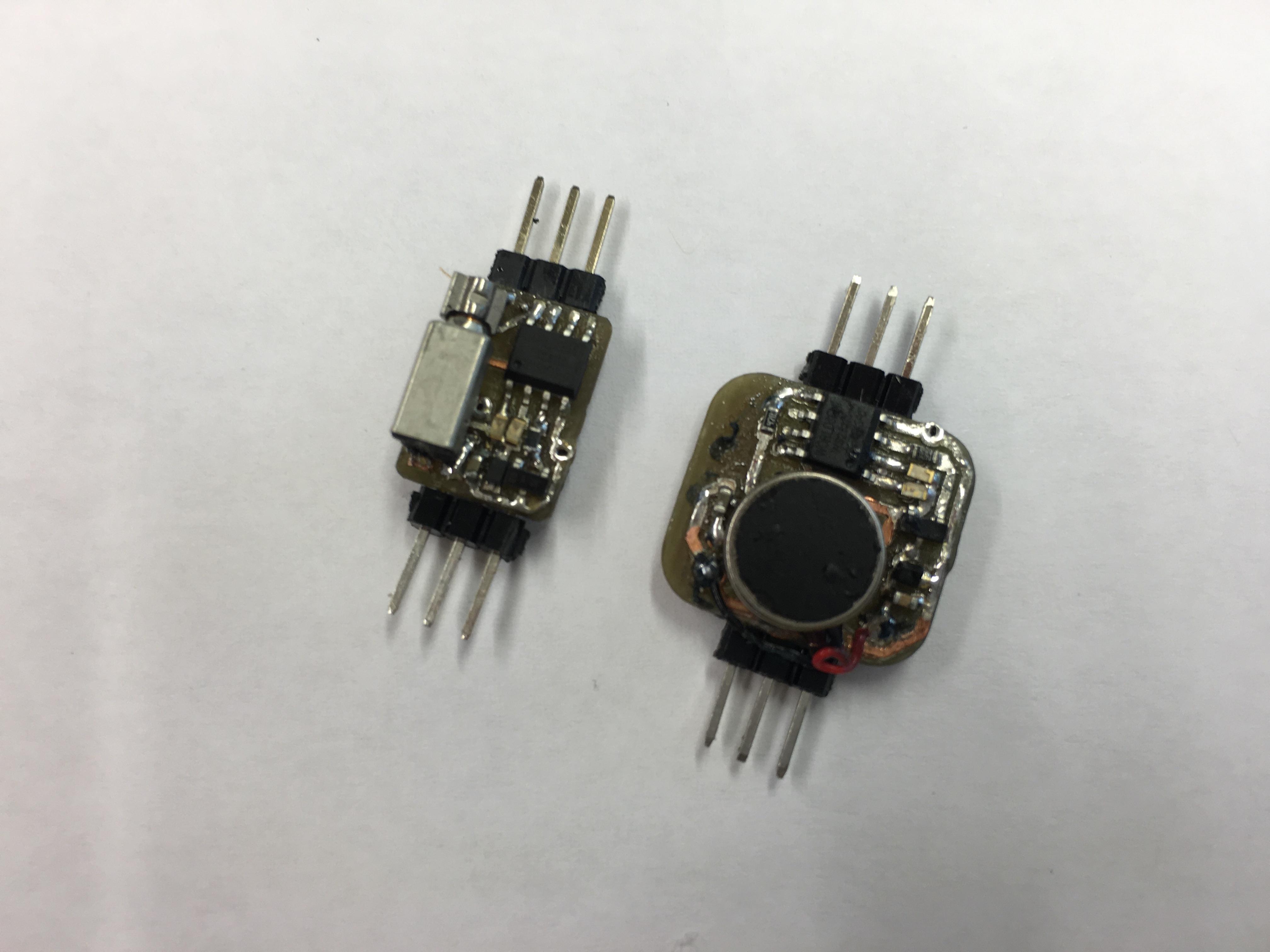
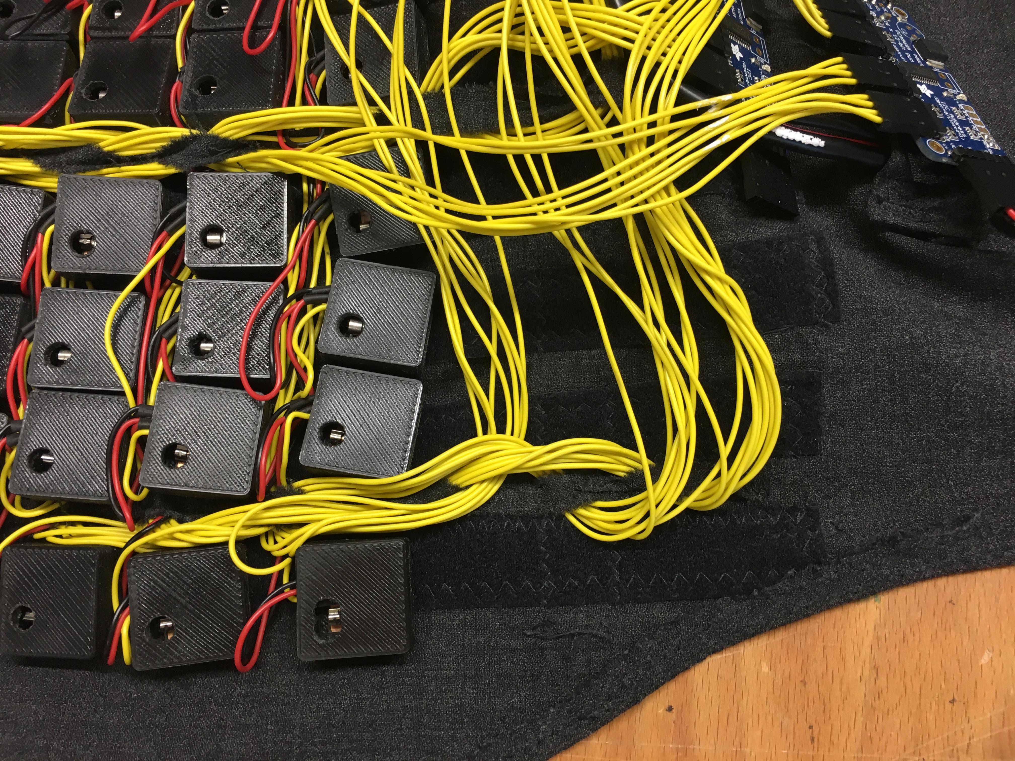
The OpenVNavi vest used PCBs with an amplifier circuit (shown on the left) in a 3D-printed housing for each vibration motor, which was mounted on the PCB within the housing. This allowed the use of cheap surface mounted vibration motors, but needed both power lines for voltage supply and a data line for each motor.
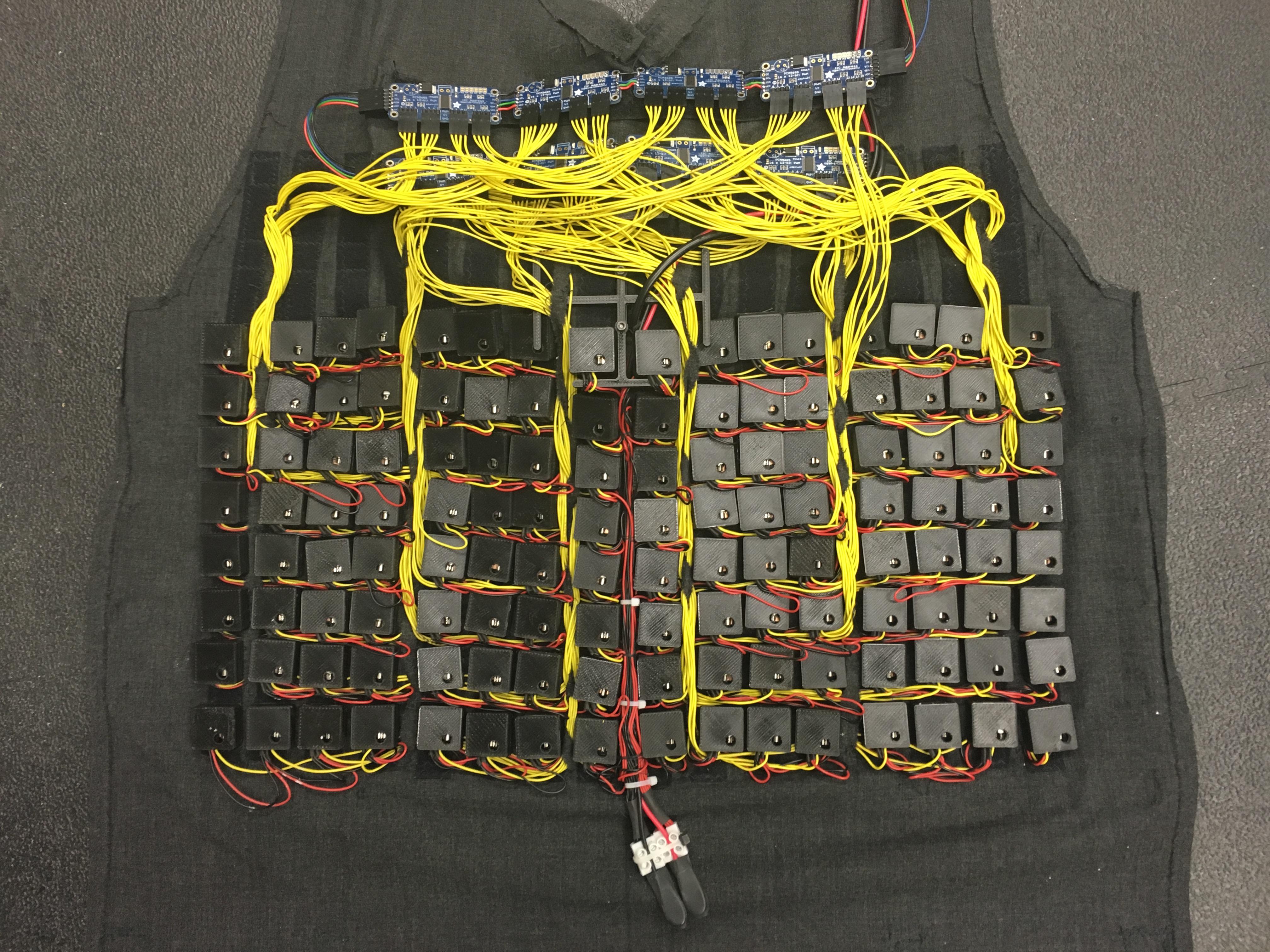
The standard 3pol pin header allows an easy exchange of these motor units (along with the velcro attachment of the housing and vest). Each half row is connected with the two supply lines in parallel, which are bundled in the middle in a central node as one power supply line, while the data lines go in between the housings upwards to the controller unit.
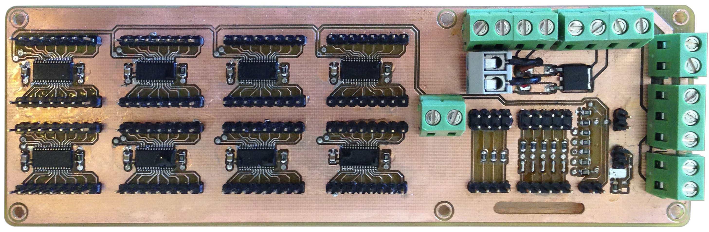
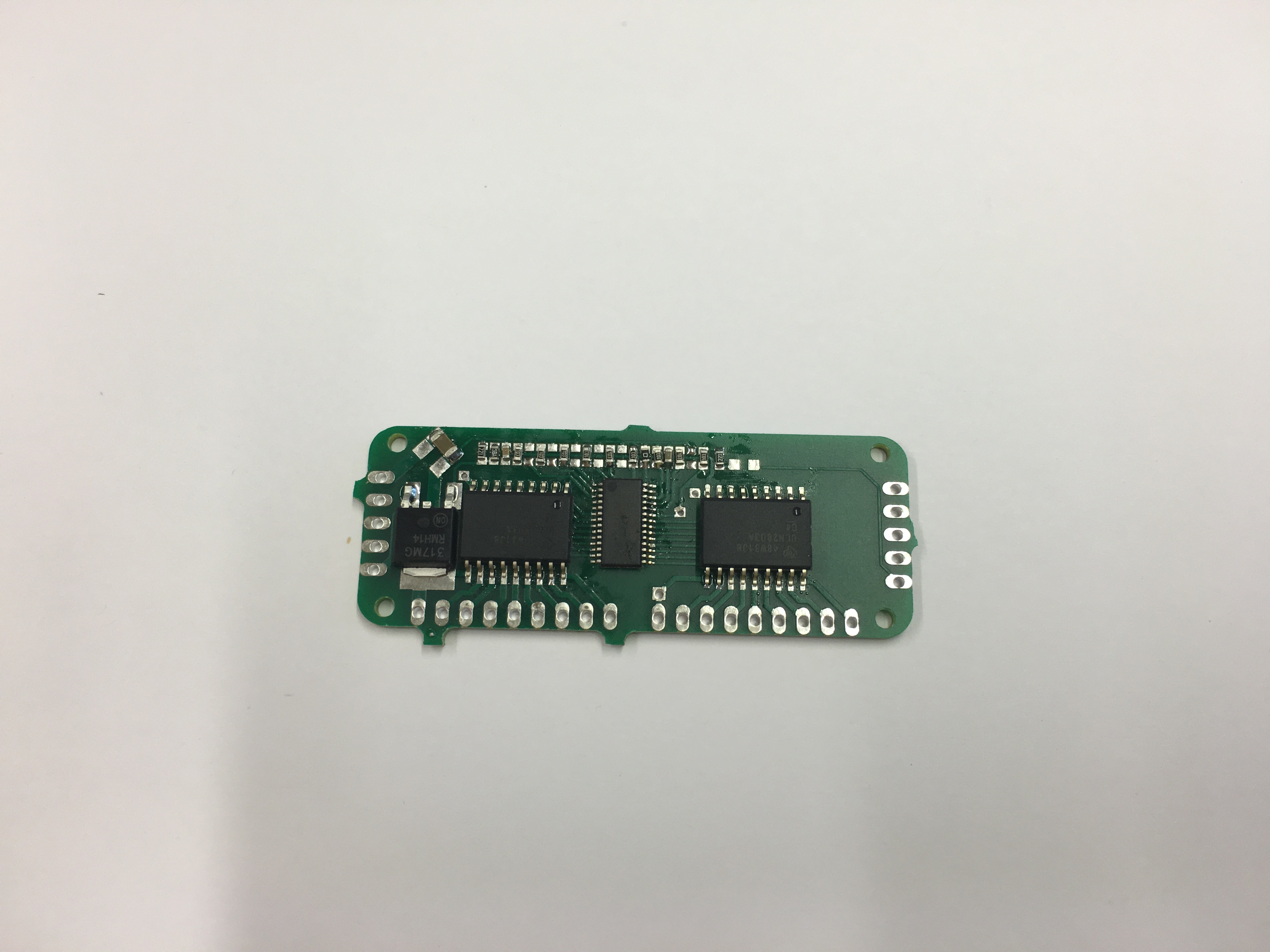
In the OpenVNavi vest, a central unit (left picture) is placed in a box at the back, where each of eight 16* I2C PWM-driver on a central PCB controls one row of vibration motors. The layouts and schematics for both boards can be found here, as well as the files for the 3D-printed housings. A more detailed description is available in his thesis.
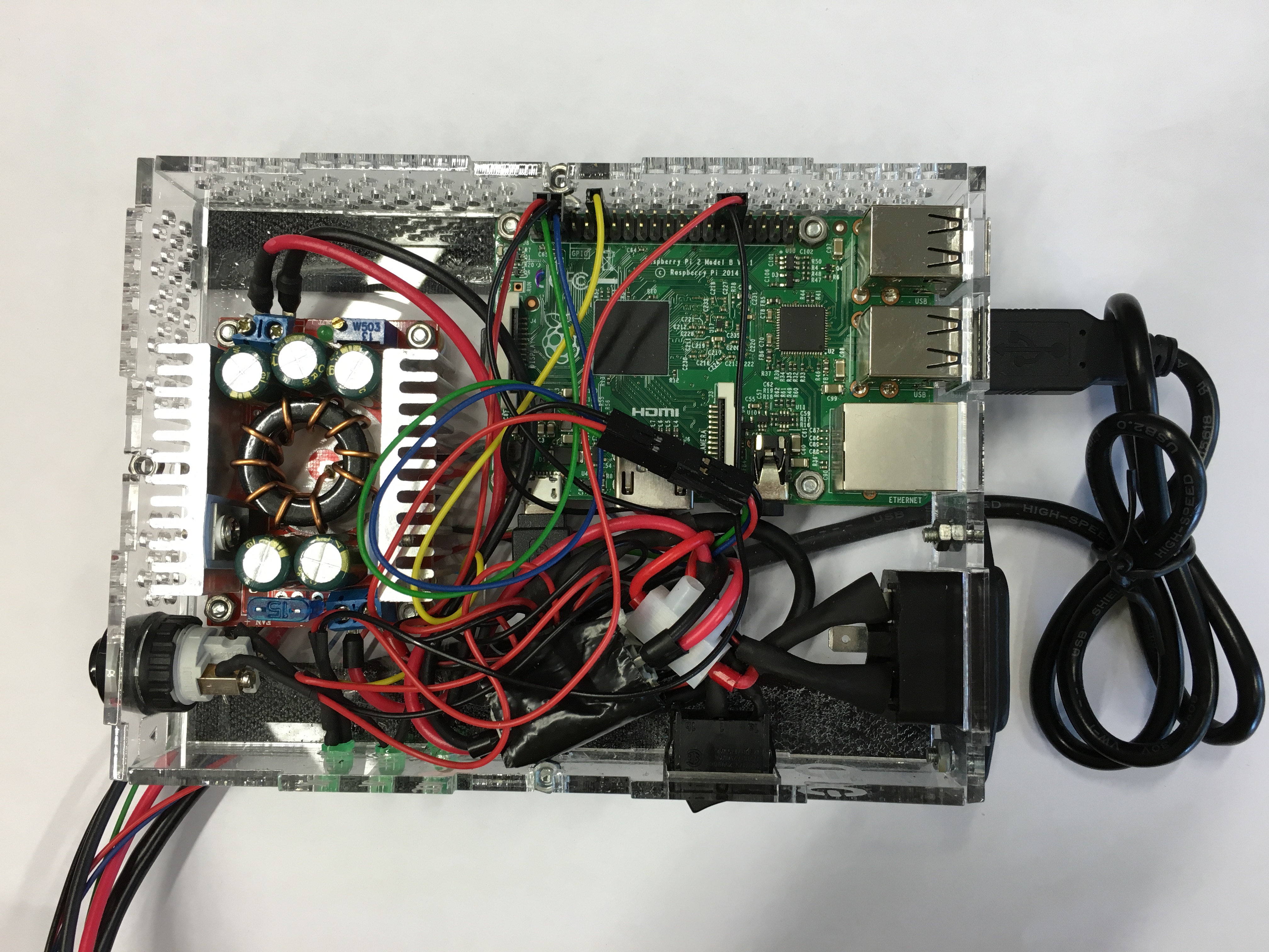
To reduce the amount of wires and simplify the exchange of driver units, this board was later replaced with standard Adafruit 16* Servo boards, which also significantly decreased the size of the back box. As a result, the back box now only contains the Raspberry Pi as brain and a Jtron buck converter for the power supply, which could either be a battery pack or cable connection.
Personal Photonics: Haptic Toolkit
We have so far developed different approaches to use huge numbers of vibration motors. PCB layouts and circuit diagrams for these approaches can be found here. The goal is to develop an easy-to-use toolkit that different kind of systems with huge numbers of vibration motors can utilize with a reasonable amount of effort.
- I2C PWM driver
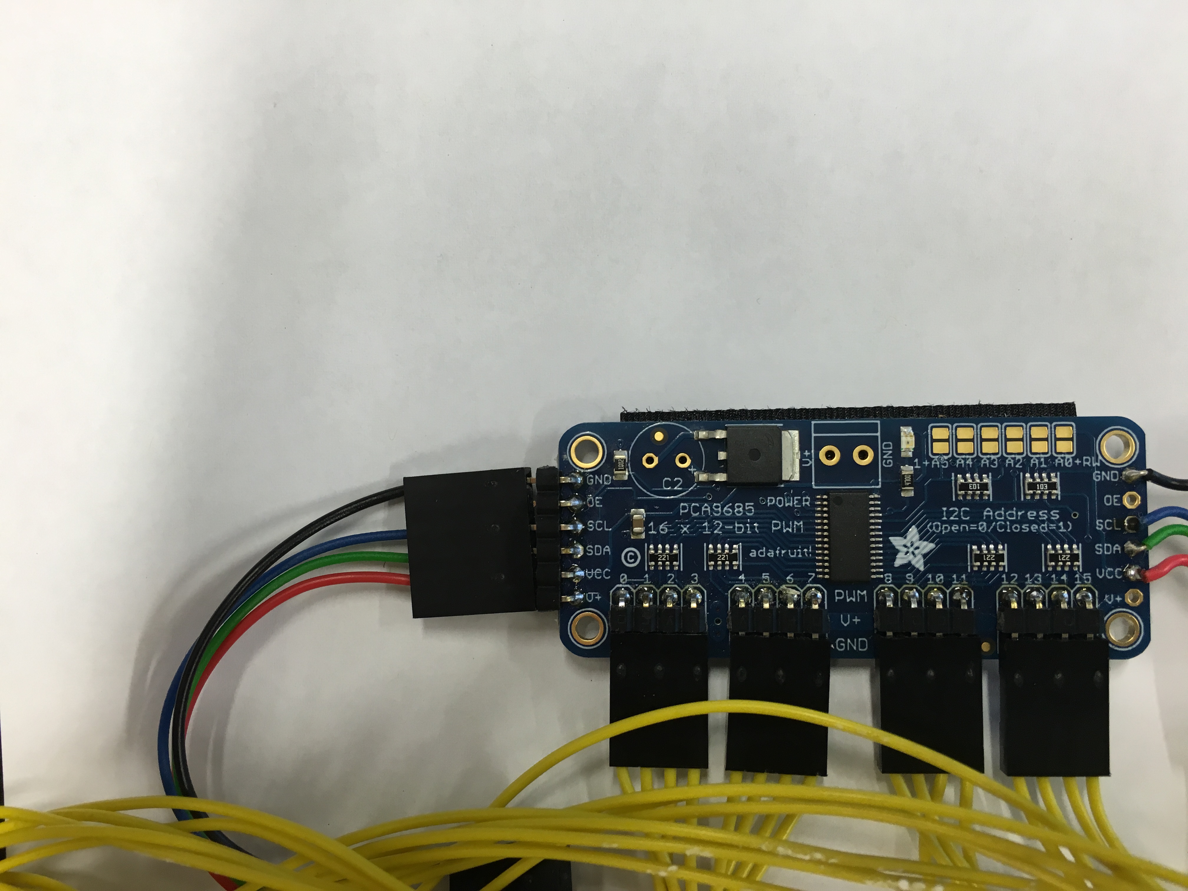
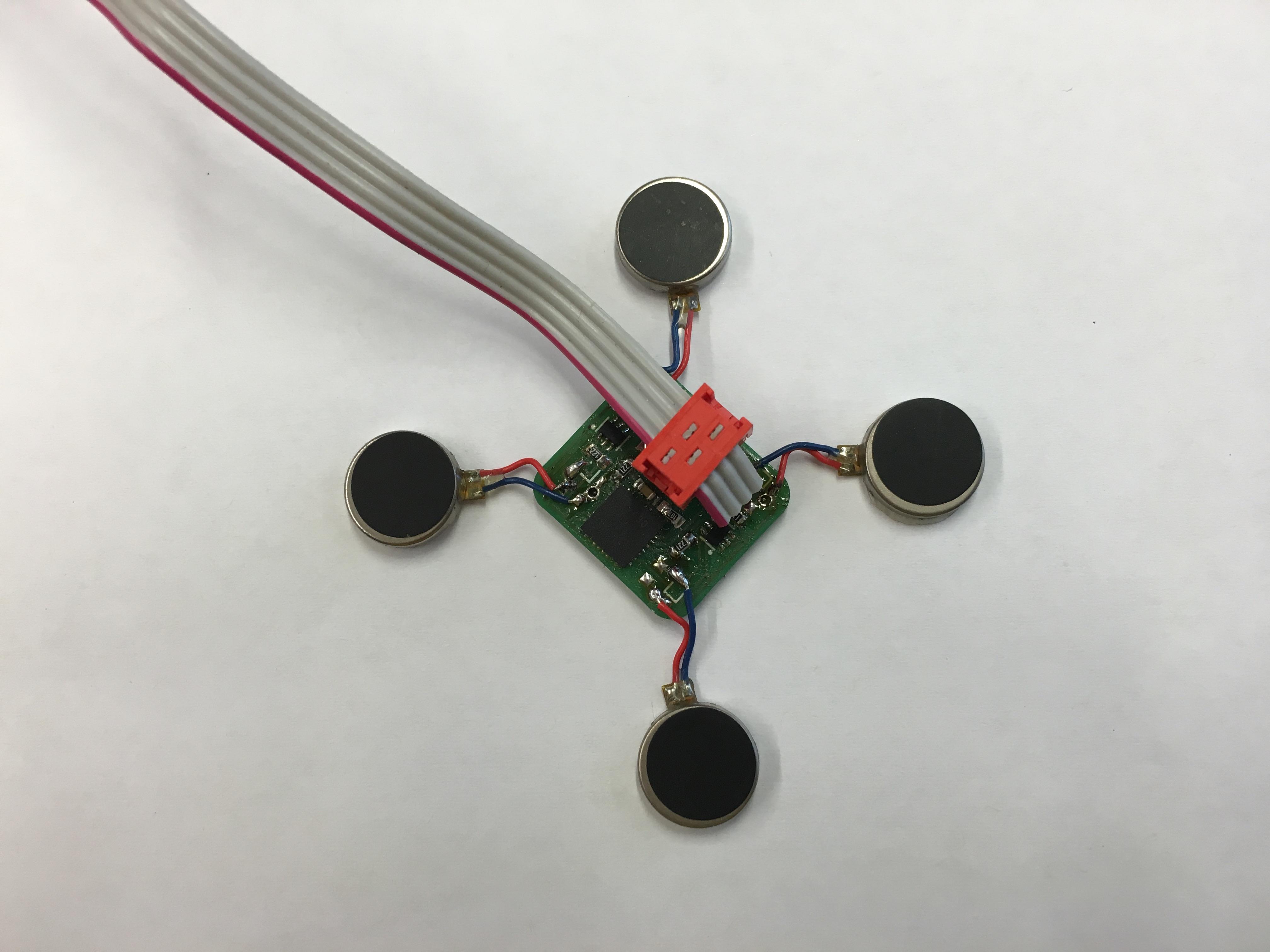
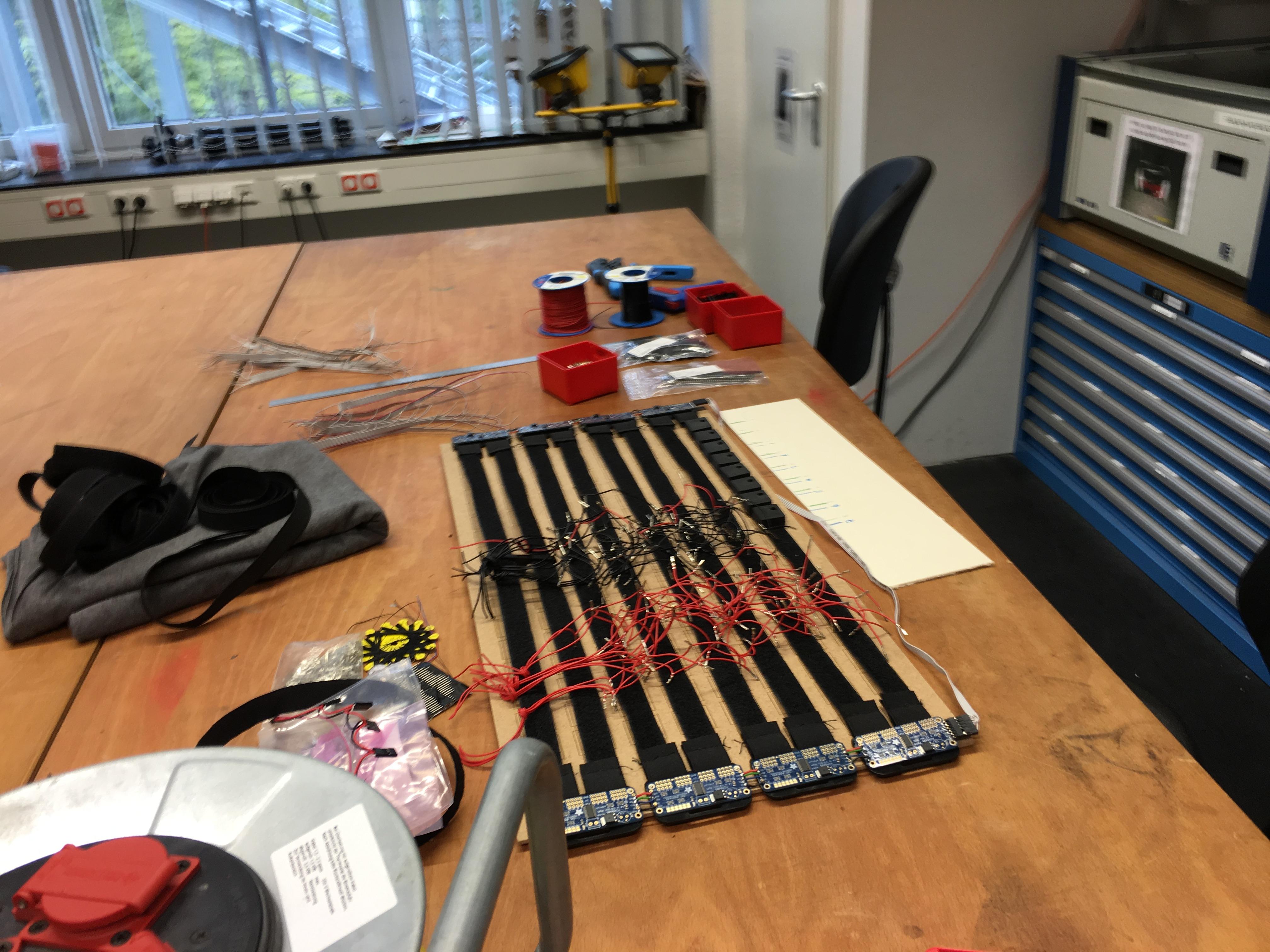
This driver can be used in the same way as the Adafruit 16*Servo driver, because it uses the same controller. However, it has an integrated voltage regulator and driver for the vibration motors, such that either encapsulated or pancake vibration motors can be directly connected with the board. Six address pins (solder on resistor) allows to use up to 62 of these boards at one I2C bus. For wiring, we use a flexible wire, and stabilize the solder joints either with shrink tube (on the vibration motor side) or hot glue (on the board itself). These boards are then interconnected with each other, and e.g., with the Raspberry Pi, with the two voltage and two I2C lines. Since a voltage converter is on each board, we don't need the bulky central unit anymore and can supply a higher voltage to each board, allowing the use of cables with smaller diameter. This is, at the moment, our best way to control the arrays of vibration motors, because of the reduced number of components to solder and the simpler wiring.
- Serial Connection
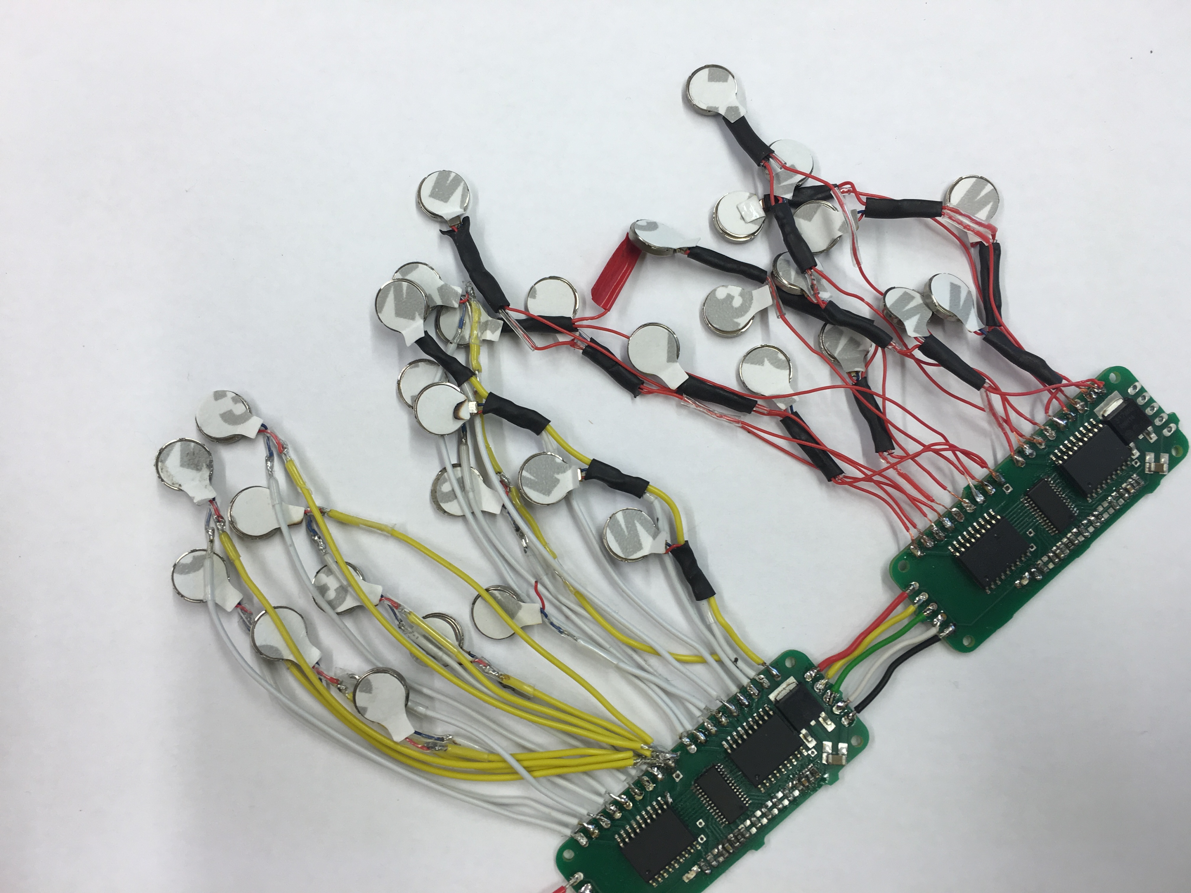
Here we use the WS2811 driver, which is normally used for RGB LED stripes with a serial one wire data bus. Instead of an LED, we control the vibration motor with this IC. While it is possible to control up to three motors with one IC (i.e., one for each color), we decided to control just one and add two single-color control LEDs instead. Therefore, we can daisy chain this board just like the LED boards, and use the same libraries and programs like the Adafruit Neopixel library to control them, up to 1024 at one data pin of a micro controller. The main disadvantage of this approach is that due to the serial connection, if one board dies, the other boards will also be dead. Therefore we recommend it only for 'non-wearable' solution, where the wiring won't be stressed too much, or use cases where the motors are spread over a big area. One wire data lines and the two voltage lines connect each board in series.
- Parallel Connection
A dedicated micro controller on each board controls up to four vibration motors. Since the PWM is now done with a general-purpose controller, we can control even linear resonant actuators, which is not possible for the above mentioned systems. A micro plug system for flat ribbon cable allows an easy setup with crimping 4 pol connectors in parallel on a cable, for the voltage, the serial data line and for programming the micro controller. Since the current supply on a standard ribbon cable is limited, after a certain number of vibration motor boards, a voltage controller board is plugged in-between (again with the same micro plug system), which converts a higher supply voltage down to the 3.3V needed for the boards, reducing the current on the supply lines. Each controller will just listen in parallel for commands, allowing them to work even when some of them break. While we have a highly adaptable wiring system in place that allows reuse of boards for different setups, the boards are harder to solder by hand, and one has to program each board individually since each controller needs a unique ID to be individually addressed.
Wiring
While the original OpenVNavi vest used standard 0.14 mm{SUP()}2{SUP} stranded wire with pin header connectors for the vibration motor boards, this is too stiff for direct soldering on the vibration motor cable (which is necessary for the I2C expander boards with integrated driver), because the vibration causes the solder joints to break. Additional reinforcements with shrinking tube and additional fixation on the textile reduces this problem, but since a bunch of wires are used, the system will be overall stiff and heavy, and coupling between the different motors might occur via the cables. Therefore we decided to switch to smaller 0.05 mm{SUP()}2{SUP} stranded wire. Note that a stranded is very important in this case, since otherwise the cable itself will easily break. After several tests, we have, at the moment, settled on a 0.04 mm{SUP()}2{SUP} twin wire for each vibration motor, which is easier to solder than the version with a common wire, allows cleaner routing for detecting faults and allows easier repairs in the future. (Please see the next subsection for the corresponding image.) Special thanks to Ceyda who had to do this nightmare of a soldering.
Haptic Image Resolution
In the original OpenVNavi vest, David took a 4 cm distance dependent on the two-point discrimination threshold of roughly 3.5cm on the human belly according to Kandel et al. 2013. The grey color values of a depth image are then mapped to the PWM values for driving the corresponding vibration motor.
For a more specific approach, the distance between the motors could be made smaller or bigger if different body parts are used as display area. Or they could be tailored to a specific user, if such a system is meant to be used by one person.
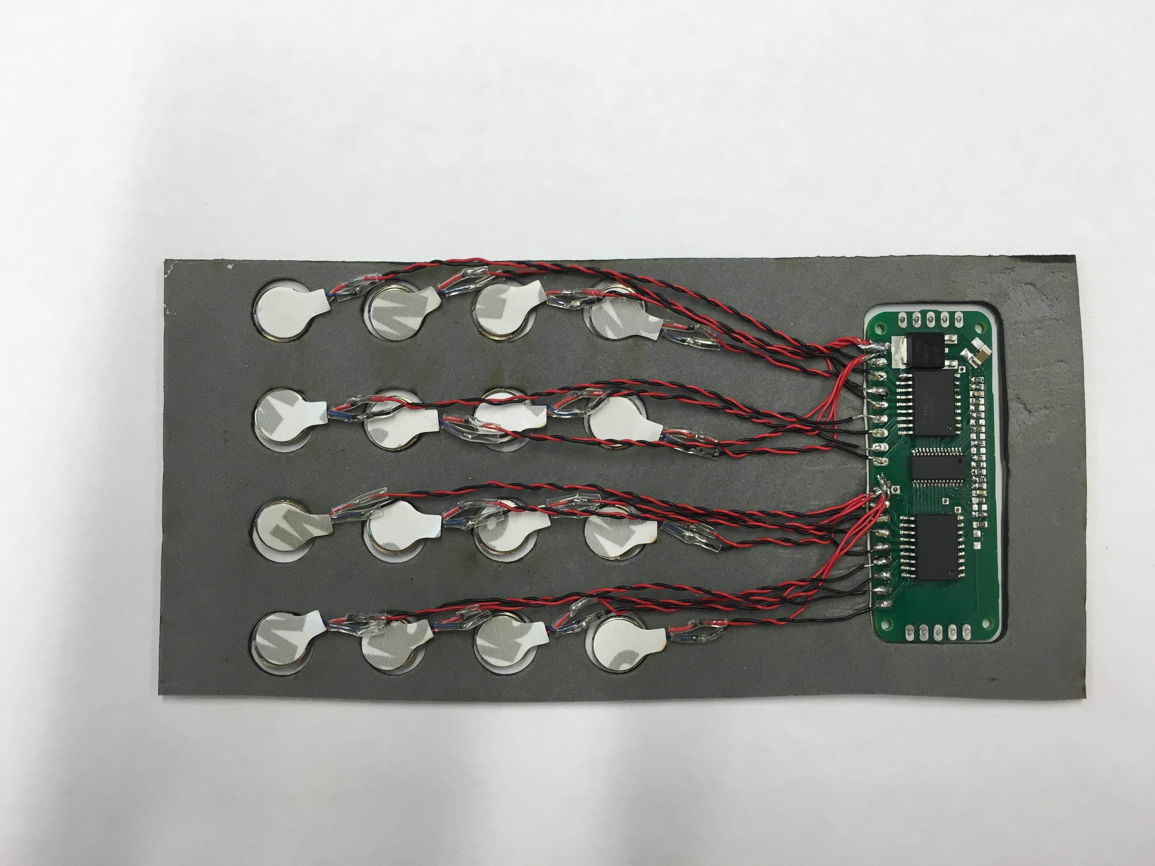
To determine the optimal distance, and to verify the validity of the 4 cm distance, we developed a test setup: A matrix of 4*4 vibration motors, driven by one I2C driver is placed within a laser-cut form of rubber foam. This allows for precise control of the distance between each motor. Since far smaller distances are used than the expected distance, we can try different patterns on it and determine at which distance, we can detect the feedback in a reliable manner. E.g., if the first and thereafter the second row of vibration motors is turned on and the user couldn't feel a difference, this distance between two vibration motors is too small and shouldn't be used in the planned layout. Both changing the position of a line of vibration motors with or without a pause in between can be tested, for both the general detection of in image and to detect motion in a haptic motion picture. The user has to then decide whether the change in position occurs. The whole system is then attached to the user's body using a velcro tape.
With a second set up, we can determine the possible "color depth" of the haptic image i.e., the PWM or power level which the user can distinguish. Here the power level of one vibration motor is changed and the user has to decide if the resulting vibration was different (weaker, stronger), or unchanged. To have the vibration motor attached to the skin with a certain amount of pressure, we found that the best way is using a certain hanging weight around the system to attach it to the arm or leg (e.g., when seated). The pressure could be modified for different users. Another option is to just use the velcro tape to attach the sensor on to the human body, from where the user can then customize the pressure settings. This information results in a reduction of communication and processing if different sensors and image processing techniques are used.
Sensor Input and Processing
The original OpenVNavi vest used an Asus XTion depth camera, which is relatively smaller than Haptic Vest 1.0 and runs on USB power. Since only USB 2.0 is needed for the camera, a Raspberry Pi can be used to process the data. The instructions for setting up the Raspberry Pi can be found setup in this Git repository. As long as either the Adafruit 16 * Servo boards or our I2C PWM-driver are used to control the vibration motors, and each driver represents one row of vibration motors, with an ordered address range from 0x40 to 0x48, you can just use the software on the repository without any modifications.
For more generic layouts, we will modify this software to allow for an easier setup where, e.g., you can change which connection is used (I2C for the I2C driver, RX/TX for the parallel driver, or one generic pin for the WS2811 variant). As a part of future work, we are also planning for a simple mapping function between the hardware and software.
Another important upgrade that we have planned to do in the near future is the option to add other sensors, either additional depth cameras - because of the field of view of the cameras at the bottom and head height disappear from the sensor area when they come closer, which is not ideal - or other sensors to circumvent certain limitations of the depth camera, e.g., it can't see glass. Options include using ultrasonic sensors for short distance warnings or using two normal cameras mounted on, e.g., shoulder, for a stereoscopic depth image.
The Asus XTion might be replaced in the future with an Intel RealSense camera or other advanced sensors. However, most of the newer sensors use USB 3.0, which is not compatible with the Raspberry Pi at the moment. Therefore it might be necessary to switch to a different controller like the Odroid XU4.
In our vest, the depth camera is connected with one of Raspberry Pi's USB ports; its I2C port (pins 3 and 5) is connected to the I2C PWM expander in a row, which in turn is connected to the individual vibration motors. Power connection is achieved by either an external power supply or a racing battery pack, which has a power supply of 7.4V. The 5V USB power banks will not be able to deliver enough current. While the original version has Pi and vibration motors supplied with a Jtron buck converter, for the versions with distributed voltage controller, we need another one for the Pi, a standard 5V/3A DC/Dc converter should be enough as long as no more (USB-)devices are attached to the Pi.
The last minor thing to add is a button to enter into a low-power mode, which turns off the vibration motors, at GPIO18, or pin 10 on the GPIO header, which is internally pulled low, therefore a connection to 3.3V of the Pi is sufficient, but an additional hardware pulldown with a 10k resistor to ground is of course additional possible.
Textile The OpenVNavi vest had to be adaptable to different body sizes, all the while making sure that the vibration motors are pressing down on to the body. Therefore the vest was made out of two sheets of stretch fabric with a sleeveless shirt pattern that were stitched together at the shoulders. We later replaced the seam on the shoulder with velcro to accelerate the process of wearing the vest during the demo sessions. On the belly, velcro strips are used to bind the vibration motors, and fasten the vest front and back with overlapping velcro strips at the sides. The depth camera is then mounted with a small 3d-printed holder on the upper body area, while the Pi and voltage regulator case is located at the back with a battery. This is again connected together through velcro strips.
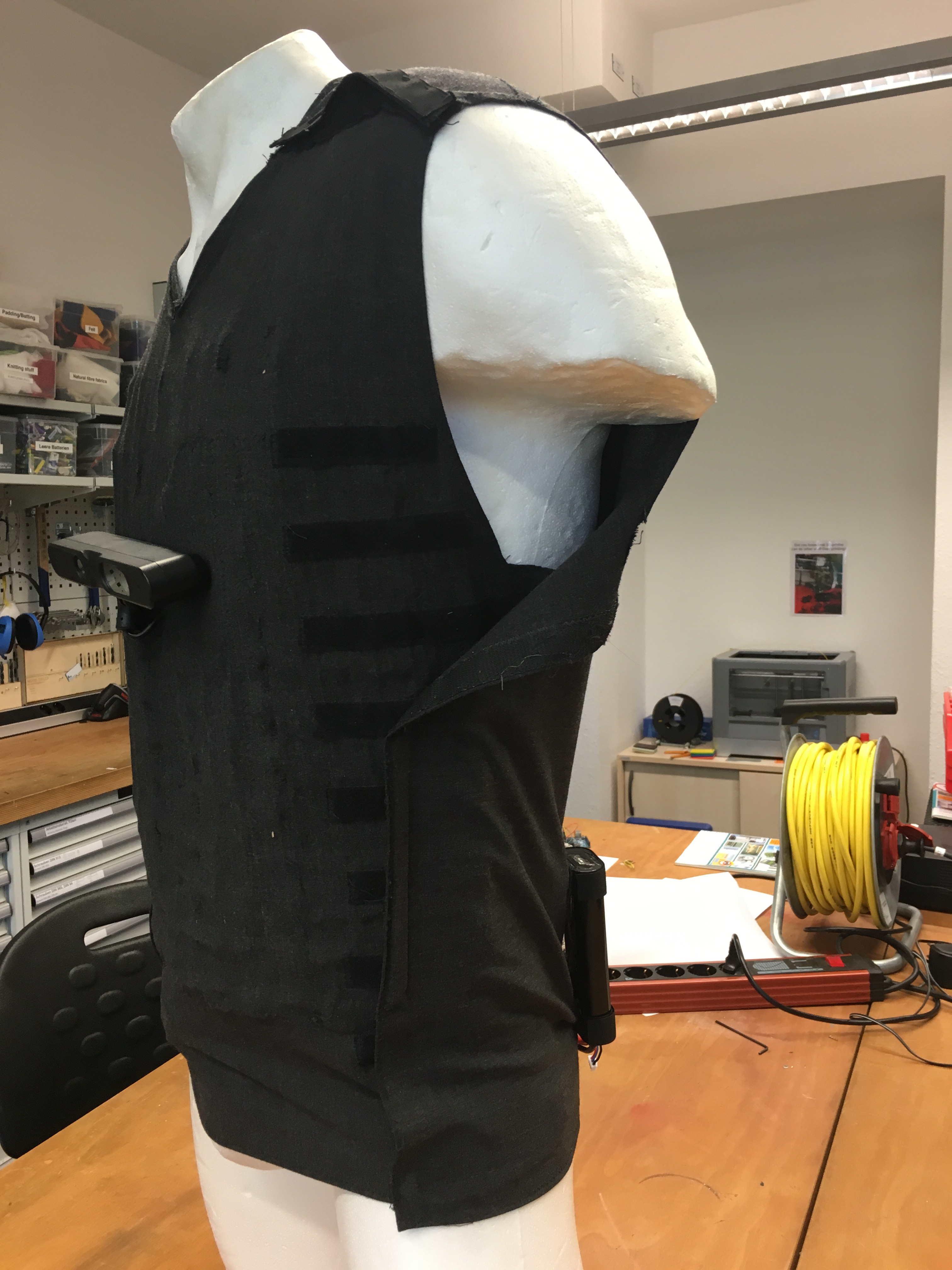
A lighter version of our vest with encapsulated vibration motors and a newer I2C board might be similar to a belt that can be worn around the torso. The I2C boards can be mounted on the sides of the belly on small laser cut boards (e.g., out of POM for stability reasons) with two strips of velcro in between, on which the motors are mounted. These strips are sewn on to the laser cut board with a small stretchable band to mould it to the shape of the belly. On the two upper straps is a mount for the middle camera, and each pair is connected with a 2 cm lashing strap on the back, which allows for fastening these pairs. To keep the vertical distances between the vibration motors constant, the velcro strips have to be sewn on to a piece of stretchable fabric again.
This process can be much simpler for a personalized version because one just needs a tight stretchable shirt, on which the vibration motors are either sewn into pockets, or even simply glued on. The bigger advantage, however, is that there is no need to make the vest fit to different body sizes.
Feel free to contact Jan Thar for further information.